Partners:
Jacob Pridmore
Our project was to create a 2-bar
linkage that moved via a dc motor. The project was made with an Arudino
Uno kit for the micro controller, dc motor and electrical components.
Several structural parts were produced out of cardboard with either
through a laser cutter or made by hand.
My role was to complete the micro
controller setup on the system by wiring and programming a dc motor and
switch to Arduino.
I used the project 9, motorized pinwheel, to create the circuit and source code. I followed the steps up to the point where the pinwheel apparatus needed to be attached (the apparatus was not attached because we needed to attach the motor to the linkage mechanism). The code for this project is identical to the source code used for project 9 in the book.
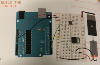
Image of the circuit from the Arduino projects book:
Process of building circuit:
1. Obtain materials:
- Arudino Uno micro controller
- Breadboard
- 8 wires
-Positive and negative ground wires
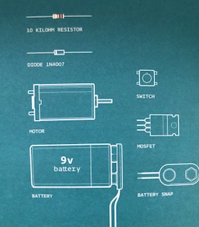
Electrical components:
2. Connect positive ground wire into the 5v port on the Arudino and connect the negative ground wire into the ground port on the Arudino
- Connect the positive and negative ground wires into the positive and negative ports on the breadboard respectively
3.Connect wires as shown in the image of the circuit
4. Connect switch as shown
5. Connect resistor as shown
6. Connect MOSFET as shown
7. Connect Diode as shown
8. Connect dc motor as shown
9. Connect 9v battery snap and 9v battery as shown
Programming:
Source code from Arudino Projects book:
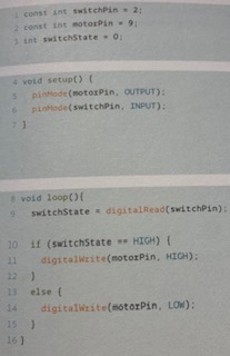
1. Identify constraints
-Set a constraint switchPin equal to 2
- Set a constraint motorPin equal to 9
2. Identify variables
- Set a variable switchState equal to 0
3. create a setup
- The pinMode of the dc motor will be declared as an output
- The pinMode of the push button switch will be declared as an input
4. create a void loop
- The switchPin function state and the digitalRead state will be determined together
5. Create an if statement
- Set the motorPin function to HIGH
6. Create an else statement
- Set the motorPin function to LOW
I also supplied most of the building materials used in the project.
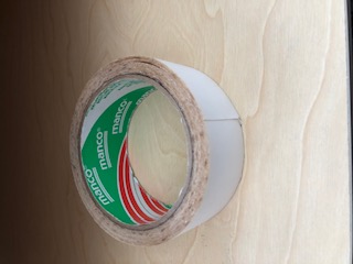
List of Building materials that I supplied:
1. Duct tape (to secure two linkage bars together to make a reinforced bar)
2. Electrical Tape (to act as spacing to increase the diameter of the axles)
3. Double-sided Tape (to connect the dowel to the linkage cams)
4. Superglue (to permanently secure parts together)
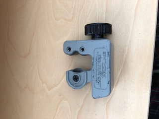
5. Dowels (for axles)
6. Pipe cutter (to cut the dowels to length)
7. Scissors
A failure that occurred was that one of the partners in the group was not able to attend a lab session to work on the linkage. This was solved by introducing another member into the group, creating a group of three. The other group member arrived at a later time outside of class to help finish the project.
What I learned is that we do not need to reinvent the wheel. We used past designs and re purposed already existing parts to make the project cheaper and more efficiently.
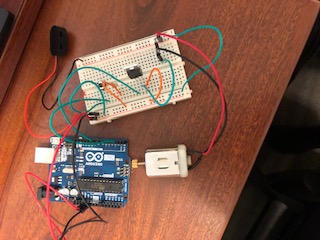
Image of Circuit built:
.ino file of the Transformer code
Video of the circuit and motor setup
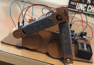
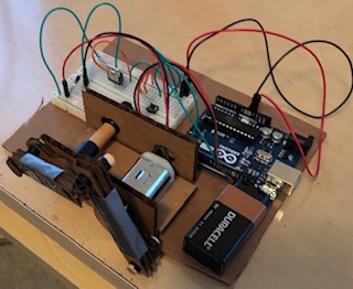
Picture of final project:
Video of the final project:
Answers to questions:
I liked the teamwork aspect of this project. The project allows us to collaborate with other people, which is what will occur in industry. There will be teams of people that design a system or assembly. I also like that the project utilizes many different resources including a micro controller (we used the Arduino Uno) and laser cutter to produce the project.
There were a few challenges of the project. The dc motor supplied with the Arduino beginner kit spins relatively very fast, but has very low torque. Therefore, the motor could not spin with enough power to rotate even just the weight of the two linkage bars, let alone the entire system. this was matched with high friction in the system, because of spacing issues and the materials being high-friction surfaces. the corrugate in the cardboard induced friction, as well as the electrical tape wrapped around the dowel.
there were also several spacing issues. First, the dowels were not properly sized to the holes that were produced. Electrical tape was wrapped around the dowels to make their diameter larger, but created more friction in the system. The other issue was that the pieces were not properly mounted along the dowel axles, creating more torque.
Only a push-button switch and MOSFET were used as sensors. Only a push-button switch was used because the motor did not need to turn on by a change in its environment, only through human manipulation. A MOSFET was used to direct the electrical current in only one direction so that the motor could only spin in one direction. It is essentially an electronic anti-reversal mechanism. This minimizes wear on the motor and is needed in applications where the motor needs to only move in one direction.
The Arduino dc motor was used as our actuator in the project. The dc motor provided rotational force used to move the linkage bars.
I would like to learn more about how to create a system that can create this mechanism in a more efficient and effective manner. I know that with the experience of this project, there were mistakes that could have been avoided to make production faster and create a better product.
I learned that even though this project was relatively simple, there were many things that we did not consider, such as how to properly design the dimensions of the parts and the amount of spacing needed between each part.
Sources:
2. Arduino projects book: Project 9, motorized pinwheel