Leadscrew Design
In this assignment, we were required to design a lead screw contraption capable of transporting a 10 lbf table and a 4 in block 8 inches vertically at a speed between 8-12 in/s. For our calculations we were given a coefficient of friction of 0.4 and a safety factor of 5. Our approach to the assignment was to divide the work amongst us group members.
Nick Galinus - Torque and Speed and The Dreaded Parametric Modeling.
Matt Redash - Bearing Fixture Design and Tabulating Costs.
Saul Castro - Lead Screw Nut Housing Design, Affix Nut to Housing, and Design Housing Dimensions.
To start this assignment off, Nick calculated the torque and speed of the leadscrew contraption using the equations we were given in the lecture. The calculations resulted in a speed of 9600 RPM and a torque of 1.415 lb-in. The lead screw he chose for this part was a 3/8-20 of 3ft (item number 6350K703), which goes with a 3/8-20 nut (item number 6350K172).
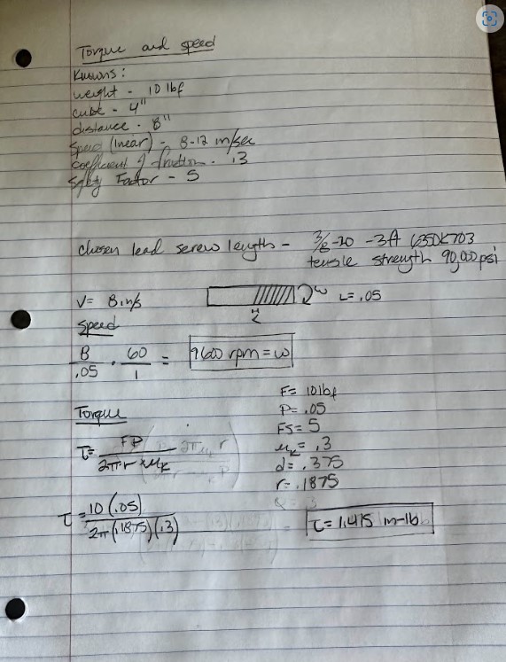
Figure 1: Torque and Speed Calculations
I then began calculating the housing dimensions for our lead screw design. The guidelines for the value n, required it to be 1-2 times larger than the outside diameter of our chosen nut. So, I multiplied the outside diameter by two and ended up with a value of 2.2in. Then I manipulated the equation for a cantilever beam with a load at the edge (Machinery's Handbook pg 261) so that I could solve for l and f. I calculated my force using the torque Nick calculated previously, and plugged everything into the equation where I got that lf^3 >0.0737in^4. Given that f had a lower limit of 0.25in, I chose 0.3in for that dimension and used that to calculate 2.73in for l. After that I calculated the bolt length using f + 5 threads and chose a 10-24 of 9/16" bolt (item 92196A243). I then realized I had forgotten to calculate the bolts for fixing the nut to the housing and quickly did those calculations ending up with a 10-24 of 3/4" bolt (92196A245).
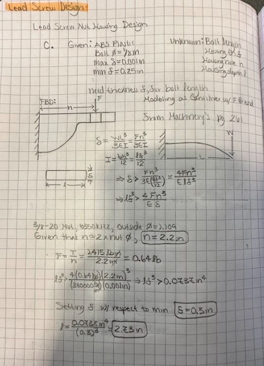
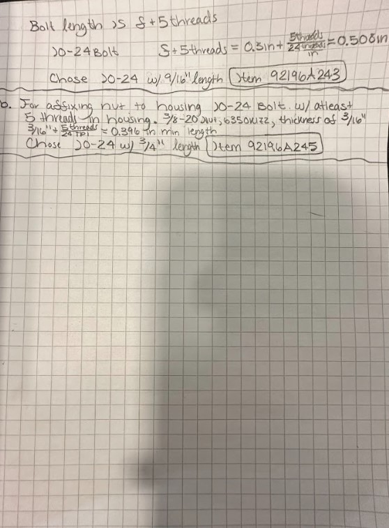
Figures 2-3: Housing Dimensions Calculations
I then came up with the rest of the dimensions using logic and rules of thumb.
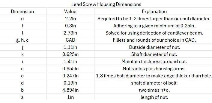
Figure 4: Remaining Housing Dimensions
For the bearing fixture design, Matt found three design options. He narrowed them down and ended up choosing option 1 because it had the most information and its pricing. He then figured out the specifics and chose the best design for our lead screw.
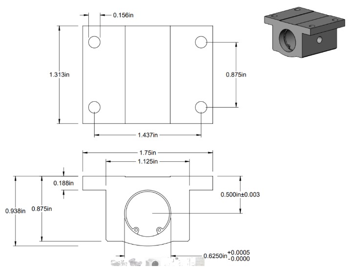
Figure 5: Bearing Drawing
Once chosen, he began calculations of the stress of the bearing on the housing and the stress of the housing on the table. For the stress of the bearing on the housing he used the area that the whole bearing was in, and the force of the table plus the cube divided by 4. For the housing on the table stress he used the diameters of the screw that we would use plus the length of the screws. The force was divided by 16 this time since there are 16 screws. The material chosen for the housing was 6061 aluminum because it can handle the stress being put on it, and it is how its sold on the website.
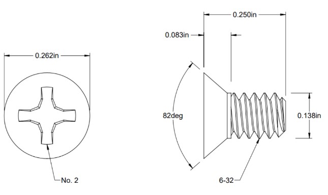
Figure 6: Screw Drawing
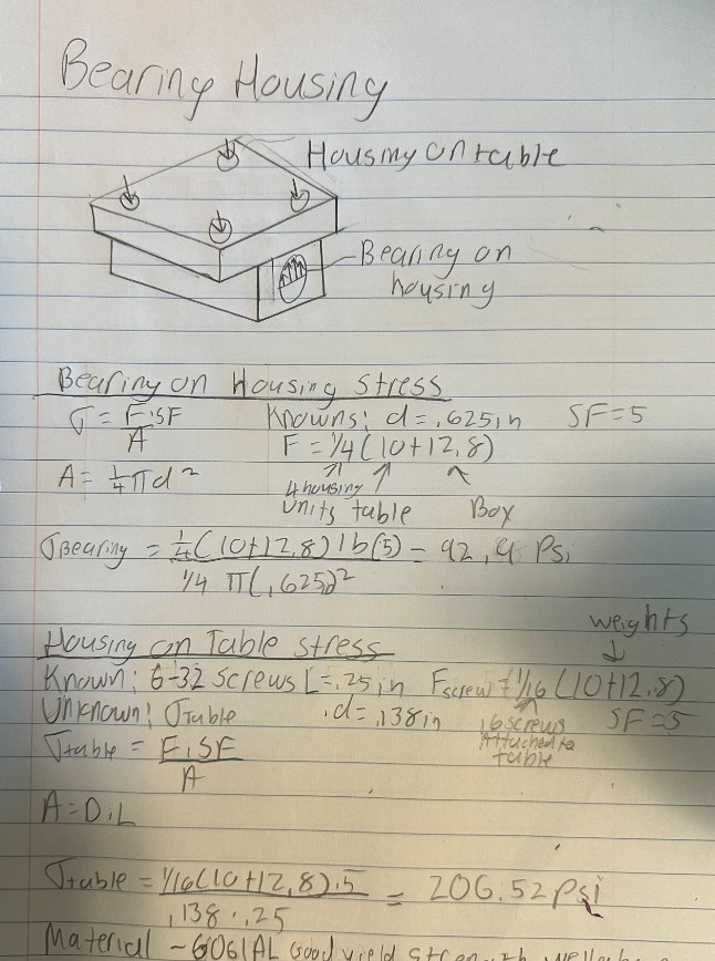
Figure 7: Bearing Fixture Calculations
Withe all of the calculations done, he put together a table tabulating all of the costs and the total ended up being $333.81 to create our contraption.
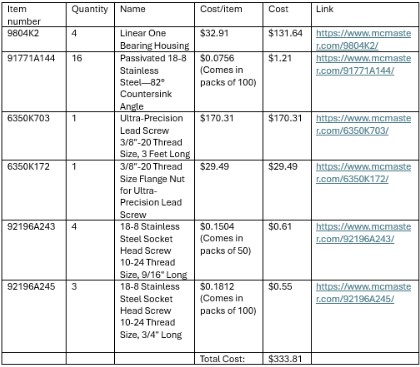
Figure 8: Cost Table
Lastly, Nick put everything together and parametrically modeled our design in SolidWorks.
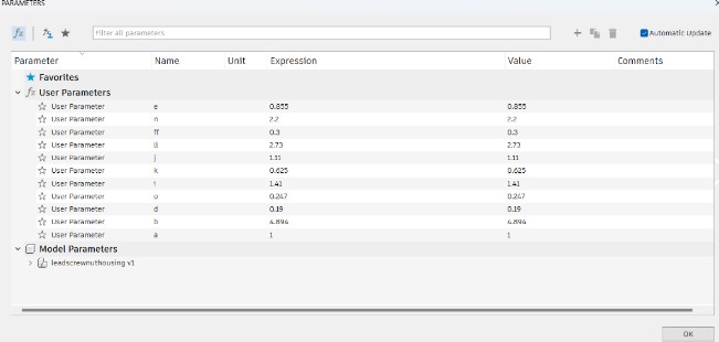
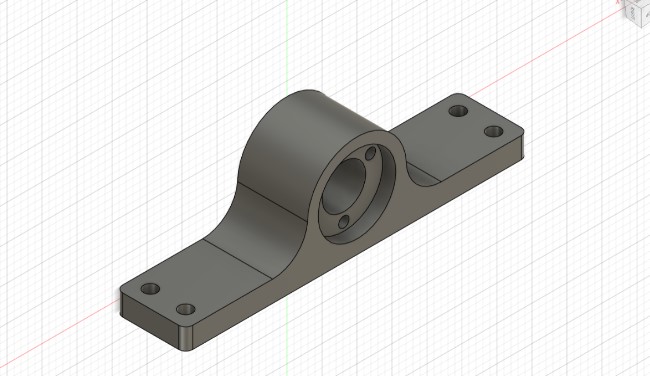
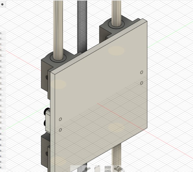

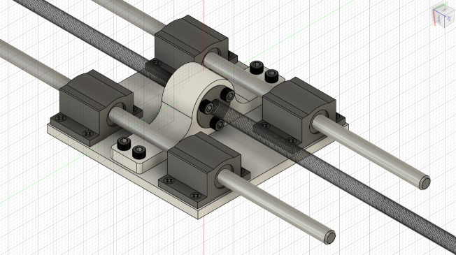
Figures 9-13: Parametric Model
Downloadable Assembly
Downloadable Nut Housing