Truss Stress Design
The purpose of this assignment was to design a lightweight planar truss using A500 structural steel according to the following specifications: P = 3000 N, a = 1.2 m, b = 0.6 m, A is a pin support, B is a roller support, no element can exceed 1m, element cross sectional areas are to be identical, and it is to be made of A500 Structural Steel.
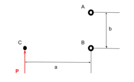
Figure 1: The force and geometric constraints
I started the assignment off by hand drawing my truss design. My plan was to split the distance, a, into two beams and to have a vertical beam in between. I did this so that I could generate three identical triangles in the truss for aesthetics, and it also helped make calculations less tedious. I then went on to calculate the lengths and angles using basic trig and the pythagorean theorem.(AD = 0.632 m, AE = 0.2 m, BE = 0.4 m, BF = 0.6 m, CD = 0.721 m, CF = 0.6 m, DE = 0.6 m, DF = 0.4 m, EF = 0.721 m)
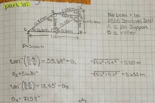
Figure 2: Design of overall truss geometry and calculations
Once I had all of my lengths and angles, I went on to calculate the support forces of my truss so that I could then calculate its internal forces. I started by doing a sum of forces in the Y direction to find Ay, since there was only one unknown in that equation. Then I did a sum of moments about pin A to find Bx, and lastly a sum of forces in the X direction to find Ax.(Ay = -3000 N, Ax = -6000 N, Bx = -6000 N)
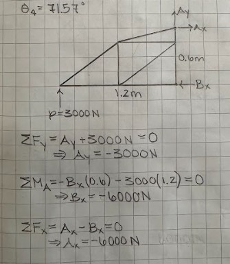
Figure 3: Support force calculations
Now that I had the support forces, it was time to calculate the internal forces of each beam. I did this by generating free body diagrams of each pin and using basic sum of force equations to calculate the internal forces. My approach to these calculations was to start with the pins that had less members attached and work my way to the more tedious ones. When I finished, I used logic to determine whether the calculations made sense or not. For example, I got a compression internal force for beam CD, which makes sense because the force P is pushing the truss up, so beam CD is gonna absorb some of it. To avoid repetitiveness, I'll include the calculations for the first and last pin I did calculations for, and my final values.(AD = 6324.37 N C, AE = 1000.58 N C, BE = 0 N, BF = 6000 N T, CD = 5408.34 N C, CF = 4500 N T, DE = 1500 N T, DF = 1000 N T, EF = 1802.77 N C)
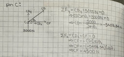
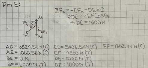
Figures 4-5: Internal force calculations
The next step was to determine the cross sectional area for my beams. The first thing I did was to write down the equation for stress which is σ = F/A. We were given the yield strength of A500 steel as 46 ksi and I used the force of greatest magnitude as my force, so that I know my calculated area can withstand every other force. I then solved for my cross sectional area by manipulating the equation for stress and converting my values to their proper units so they cancel out properly. Lastly, I multiplied the resulting area by three to incorporate the given safety factor.(A = 59.82 mm^2)
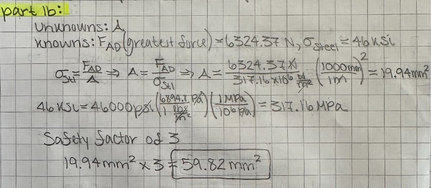
Figure 6: Beam cross sectional area calculations
I then used the cross sectional area to calculate the volume of my truss, because I knew I would need it to get its weight. I did this by multiplying the section area by the total length of my truss, which I found by adding up the lengths of all my beams. then, I looked up the density of A500 steel and it was 7850 Kg/m^3, I multiplied this by my volume to get mass and used w = mg to get my weight.(w = 22.46 N)
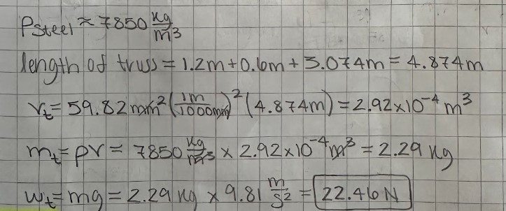
Figure 7: Truss weight calculations
The next step was to find my pin sectional area. I did this by calculating the force on the pin acting against the force with the greatest magnitude. In this case, it was pin A, and that force ended up coming out to 6708.2 N. I then chose a double shear configuration to ensure a smaller sectional area and derived the shear stress formula to account for it. Given the yield shear strength of low carbon steel as 23 ksi and the force of 6708.2 N I calculated, all that was left was to manipulate the shear stress formula to solve for cross sectional area, and to convert to proper units. I then multiplied the area by the given safety factor of 4 and moved on to calculate the combined weight of the pins.(Av = 84.6 mm^2)

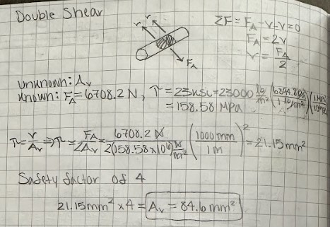
Figures 8-9: Pin cross sectional area calculations
Now this was probably one of the trickier parts of this design, finding the weight of the pins. First things first I calculated a diameter for my pins using the area I calculated beforehand, to check if it was too big for my beams. This diameter ended up being bigger than I expected, but I accounted for it by making my beam cross section rectangular. I then checked my truss design to see how many beams would connect at each pin so that I could start calculating some lengths. Pins A, B, and C had 2 beams attached so I multiplied my beam thickness by 2 and rounded up to the nearest whole value. Pins D, E, and F had 4 beams attached so I multiplied it by 4 and rounded up to the nearest whole value. I then added up all of the pin lengths and multiplied them by the pin cross sectional area I had calculated earlier to get the total volume of the pins. Having the volume, I multiplied it by the density of low-carbon steel(7861.093 kg/m^3) to get my mass and used w = mg to get my total pin weight.(w = 0.588 N)
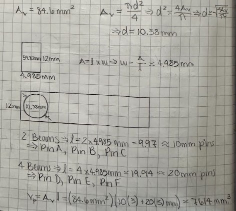
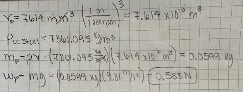
Figures 10-11: Pin weight calculations
It was now time to start the CAD model, to avoid repetitiveness Im going show the process for creating only one of the beams and pins. I started by making the rectangular geometry of the beam and extruding out the thickness.

Figure 12: Beam extrusion
I then added a centered point at the edge of the beam and made the hole for the pin to go through.

Figure 13: Pin hole
The other end required a geometry for holding an attached beam. For this I extruded two rectangles half the thickness of my beam(so I didn’t have to change my pin lengths) that sandwiched my beam and made an extrude cut in between. Then, to finish off my beam, I added a hole, and repeated this process for all other beams(the only difference being length).
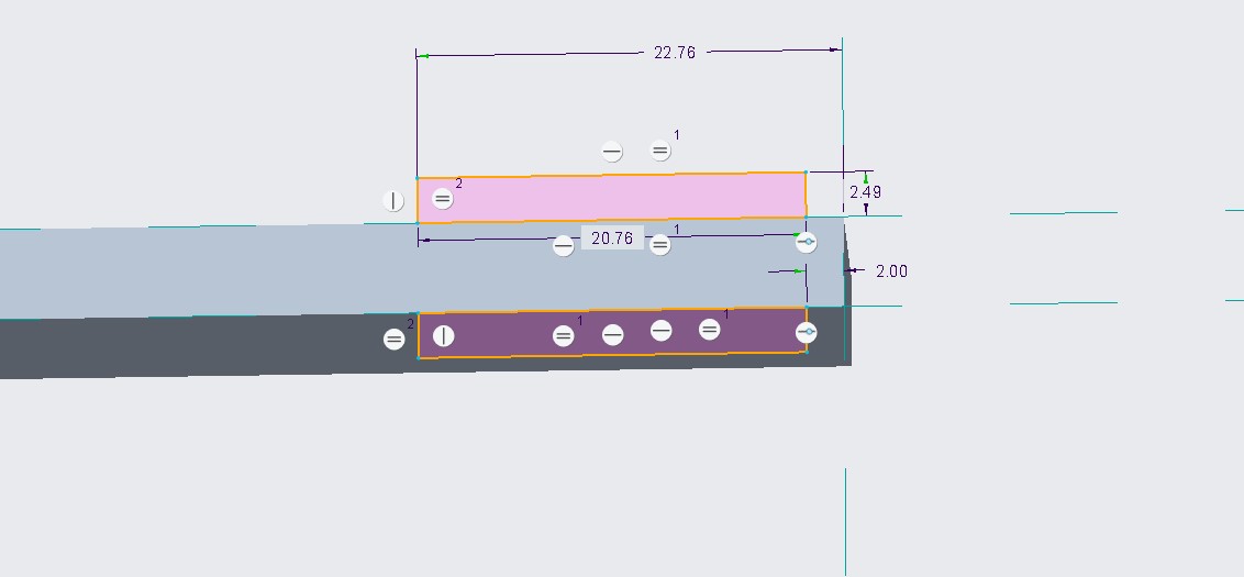
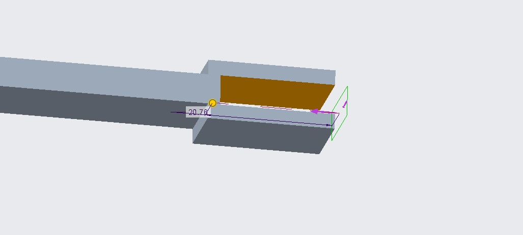

Figures 14-16: Other end of beam
The pins were a lot easier to make, this process consisted of a single extrusion.
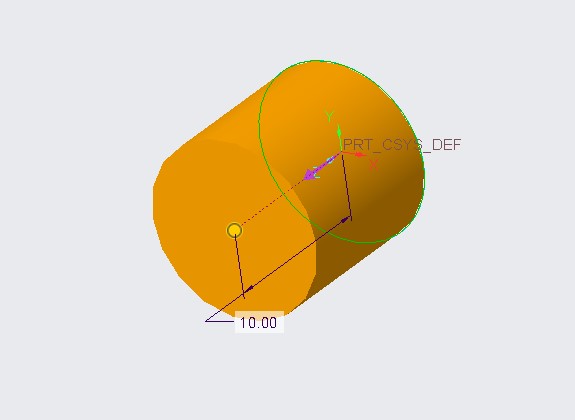
Figure 17: Pin extrusion
It was now time to assemble the beams. I started by assembling the horizontal and vertical beams since they were a lot easier to work with. Then I assembled the diagonal beams, and lastly the pins. This process consisted of coincident and distance constraints.
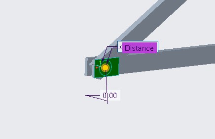

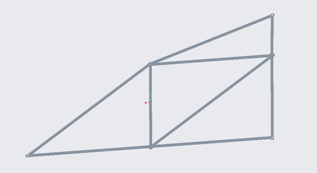
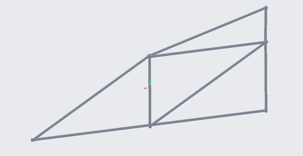
Figures 18-21: Assembly
The last part of this design was comparing the CAD weight to my hand calculated weight. For some reason the mass in creo was in Tonne, but this was no big deal since I could just convert it to kg. Converting it to kg, I got 2.082 kg and the weight calculations gave me a weight of 20.42 N on creo. I then added my hand calculated pin weight to my truss weight and ended up with 23.048 N, about 3 N higher than my model in creo. I believe this is because of the holes I made for the pins, but I wasn’t too far off anyways.
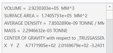

Figures 22-23: Weight comparison
Downloadable Part File