REFERENCE COORDINATE SYSTEMS AND TRANSFORMATIONS
LOCATION IS RELATIVE
An object's location is always given relative to another reference object. For example,
the location of a community park may be described as five blocks from the Post Office. To
be more specific, the community park is four blocks east and three blocks south of the
Post Office. With this illustration, a position
vector has been established, that is, a direction and a distance (spatial vector) from the Post Office. Several
things are assumed to be known: the place to begin (Post Office), an understanding of east
and south (reference directions), and the length of a block (unit of displacement). Without consensus on these
things, communication of the location of the park becomes unclear.
SPATIAL REFERENCE FRAME
A stated reference object along with reference directions and a unit displacement
length form the basis of a spatial reference frame in which the
physical location (direction and distance from reference) of an object can be
communicated.
In forming a spatial (physical) reference frame, the first thing to identify is an origin
point (Post Office in our previous example) that is associated with a real physical
object. To facilitate clarity, a specific point having no consequential size needs to be
designated as the origin. In our example, we started at the Post Office, but what if this
building were to occupy a complete square block? We could start walking from the
"incorrect" corner and thus not arrive at our destination. So we alter our
directions to specify starting at the corner that has a fountain. The smaller the object
whose position is to be described or the more exact that the position needs to be known,
the more detailed description needed for the origin point.
Second, reference directions from which we can determine the object location with
respect to the reference need to be described that cover all possible location dimensions.
For spatial frames, these reference directions are chosen to be linear. Examples of reference directions are east and north. Additionally,
we need to specify the positive and negative directions. For example, west is the negative
of east. Also, north and east do not specify a starting point, they only give direction.And since east reverses directions from one side of the earth to
the other, it is advantageous to build a reference frame in a more formal way. This will
be described in 'Establishing Direction References' section.
Finally, we must define the standard reference
unit for distance. For example, we state that
a block is 400 feet (provided we know what "feet" are). In building the location
frame, the unit of length is usually to be based upon a standard (meters, feet, millimeters etc.). A
standard unit is not necessary, but the unit chosen must be understood.
In our illustration, once we have agreed on the distance unit, the origin point, and
the reference directions, we can describe the location of the park.
ESTABLISHING DIRECTION REFERENCES
A minimum of two points are required to establish a one-dimensional direction (a line)
with a positive and negative sense. One could say that the the line
passes through points A and B with the direction from A to B being an increasing or
positive direction sense. Specification of the reference directions used in a
reference frame to relate directly to a physical system can be done through the use of
real physical datum points, lines, and/or
planes. These datums are chosen such that they can be used to define a sufficient number
of points for establishing a direction reference for each spatial dimension. Additionally,
these datums must all be rigidly fixed with respect to one another.
Examples.
- Four points (nonplanar) can establish reference directions
in the following way. Choose one point for an origin. The vectors that go from the origin point to the other
three points establish the reference directions with positive sense going away from the
origin to the other points.
- A plane, a line (not parallel to plane), and a point (not
on plane or line) can be used to establish reference directions in the following way.
Where the line intersects the plane is the origin point. One reference direction is
defined by the line perpendicular to the plane and through the origin having a positive
sense from the origin toward the space divided by the plane that contains point B. A
second reference direction is the projection of the original line into the plane with
positive sense defined by the piece of line that is on the same side of the plane as B.
The third reference line is the line that goes through the origin and is perpendicular to
the other reference lines with the direction sense given by the right-hand rule.
- For a machine, lines can be specified by spindle, carriage,
or stage axes.
Machine surfaces such as tables facilitate
defining points, lines, and/or planes. See Modeling a machine section of the tutorial 'Dimensional Metrology and Mathematical
Error Modeling for Machine Tools'.
AXES AND UNIT REFERENCE (BASIS) VECTORS
The axes of a reference frame are lines that pass through the
origin of a reference frame and extend toward the reference directions.The positive
direction senses of the axes are the same as their respective reference directions. For three dimensions, these axes could be specified as the x axis, y axis,
and z axis.
Combining the unit distance
with each of the reference directions results in unit spatial vectors called basis vectors. That is, a basis vector is a unit distance in a given reference direction.
From our initial example, two basis vectors could be defined as one block east and one
block north. These unit vectors only have a magnitude and direction, they do not assume a
place of origin and only become applied to a specific place in the context of a physical
description.
LINEAR COORDINATE SYSTEM
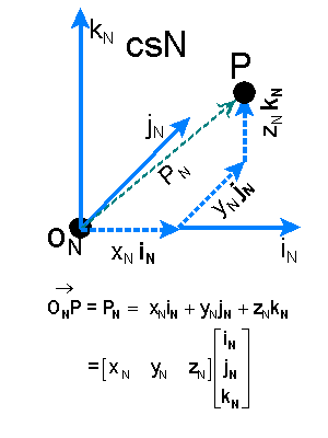 Consider the reference frame csN (to become coordinate system N) shown at the
right. The origin point is labeled as ON. P is the object for which we are
trying to define the location. The basis vectors are iN,
jN, and kN. The axes are iN,
jN and kN. The axis parallel to vector iN would be
called the iN axis etc.
Position vector PN is the
spatial vector which when referenced with respect to the defined point ON gives
the unique location of P in csN. PN is the linear combination of
displacement vectors xNiN, yNjN,
and zNkN, with xN, yN, zN
being multipliers (numbers) required to make the summation valid. Remember that iN,
jN, and kN all have the same length.
Once a reference system is agreed upon, numerical coordinate notation can simplify the
representation. The coordinate
notation of the location of P in csN is given by [PN]=(xN, yN,
zN). This is with the understanding that if the basis vectors iN, jN,
and kN were multiplied by the coordinates xN, yN,
and zN and summed together as shown below the diagram then the position vector PN from the
origin ON to P would be the result.
In our previous example, ON would be the fountain corner of the Post Office,
iN could be one block east, jN could be one block north,
and kN could be what we normally consider "up" one block.
Then, the park is at coordinates (4,-3,0) in csN or (4,-3,0)N.
Three Dimensional Rectilinear Coordinate System
In a rectilinear system, the basis vectors are chosen so that the axes are all
Euclidean straight lines which are perpendicular (orthogonal) to each other. The origin, ON,
can be defined in relation to any object we choose. It may be the intersection of two
walls and the floor. See previous diagram. For a three dimensional rectilinear
representation, (xN2+yN2+zN2)½=PN
where PN is the length of vector PN (from ON
to P) in csN units.
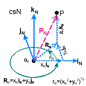 Cylindrical Coordinate Representation
In a rectilinear coordinate system, say csN, with basis vectors iN,
jN, and kN, the location of point P also has a cylindrical
vector coordinate representation which contains two length and one angular
coordinates. See diagram at right. We have position vector PN
= RN + zNkN where RN
is the the vector resulting from the sum xNiN
+ yNjN. The cylindrical representation of
point P in csN is (rN, qN, zN)
where rN is the length of vector RN, and qN is the angle that RN makes
with respect to the iN axis. qN
is positive toward the closest direction of jN. rN,
zN, and qN are known as the cylindrical
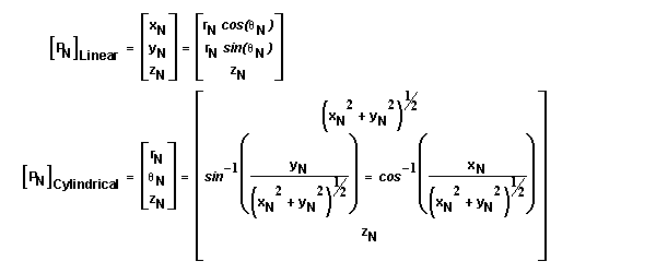
coordinates. Switching between linear and cylindrical coordinate representations
is accomplished using the following relationships.
 Spherical Coordinate Representation
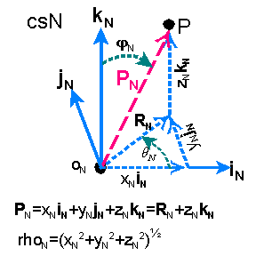
In a rectilinear coordinate system, say csN, with basis vectors iN,
jN, and kN, the location of point P also has a spherical
vector coordinate representation which contains one length and two angles. See
diagram at right. rN is the number of unit
distances between ON and P or rN=(xN2+yN2+zN2)½.
The angle between the displacement vector PN and kN
is fN. The angle between the displacement vector RN
and iN is qN as shown. RN
could be described as the projection of PN into the iNjN
plane. The positional vector in this coordinate representation is given as [PN]
= (rN, qN, fN).
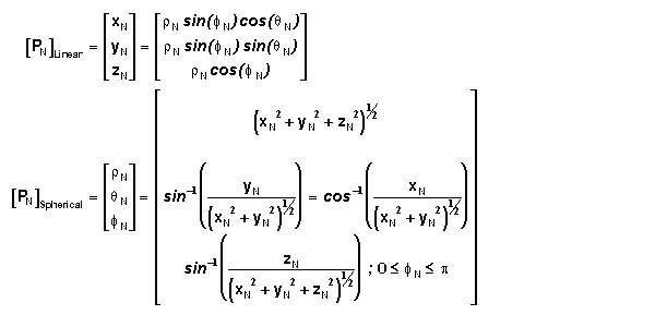
Switching between linear and spherical coordinate representations is is accomplished
using the following relationships.
Polar Coordinate Representation
A polar coordinate representation can be considered to be a degenerate form of
either a cylindrical or spherical coordinate representation. In a cylindrical
representation, if PN is constrained to be at 0 units along
the kN axis (z-axis), then PN is
represented by the simple positional polar vector
(rN, qN). Similarly, if, using a
spherical representation, PN is constrained to be at fN=90 degrees (pi/2 radians), then PN's
position is described by the equivalent simple positional polar vector (rN, qN) with rN equivalent to rN.
DUAL REPRESENTATION USING DUAL REFERENCE SYSTEMS
It is possible to locate the same point in two different reference systems as shown
below. If we have two reference systems described by csN and csM (coordinate systems N and
M), then the point P can be described in csN by (xN,yN,zN)=[PN]
or in csM (xM,yM,zM)=[PM].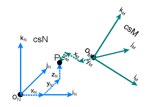
As shown, the coordinate systems need not be aligned or have the same axis description.
The axes could also differ in units (different basis vector length).
SWITCHING BETWEEN REFERENCE SYSTEMS ( BASIS
TRANSFORMATION)
If the location of P has been determined in csM, it is possible to determine its
position in csN, provided enough information is available to relate csN to csM.
Mathematically, this switching is accomplished by a transformation
of the coordinates from the csM basis to the csN basis. This basis transformation is
usually accomplished by a transformation function FMN(
). This is mathematically written as
[PN]=FMN( [PM] ).
Transformation between isometric,
aligned, but spatially separated, rectilinear coordinate systems (Simple Translation of Coordinates)
By isometric and aligned, we mean that iN=iM,
jN=jN, and kN=kM. By
iN=iM, that is, corresponding vectors have the same
direction and length. For example, both could run west-east where west is a negative
measure. This does not imply that the iN axis is the same as the iM
axis, for they are spatially separated (remember axes are defined using the origin
position). The position vector coordinates of OM in csN is [OM]N
and the position vector coordinates of ON in csM is [ON]M.
If these criterion hold, then the transformations of the coordinate representations are as
follows.
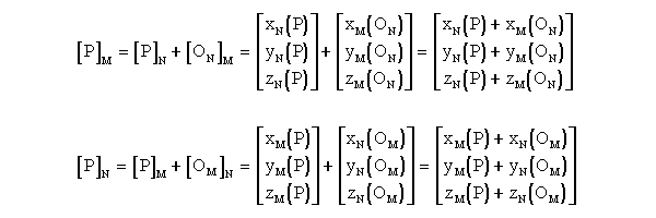
The x position vector coordinate in csN locating point P is xN(P).
Similarly, xN(OM) is the x position vector coordinate in csN
locating point OM (origin of csM). We can also define the Translational Vector Matrix from csM to csN as TMN=[OM]N,
so that [P]N = [P]M + TMN = FMN( [P]M
) for a coordinate transformation between aligned coordinate systems with noncommon
origins. Also, in this specific case TMN = -TNM.
Transformation between non-aligned isometric
rectilinear coordinate systems with common origin (Rotational Transformation)
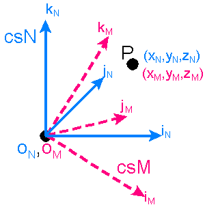 Assume we have
rectilinear non-aligned isometric systems, csN and csM, with common origins, ON
and OM, and we know the representation (of location) of point P in csM, [PM],
but we desire to determine its representation in csN, [PN]. By isometric, we
mean the length is the same for all basis vectors in csM and csN. By nonaligned we
mean that any of the iN, jN, or kN axes is not equivalent
to iM, jM, or kM axes, respectively. For example, iN
axis may run from southwest to northeast while the iM axis runs from south to
north. The diagram to the right illustrates our situation.
In order to mathematically interrelate csN and csM, we need only to determine how the
the unit reference vectors iM, jM, and kM
are each represented in csN (and vice versa) and then produce a conversion matrix for the
rotated vector basis. The following develops this matrix from the vector
representations.
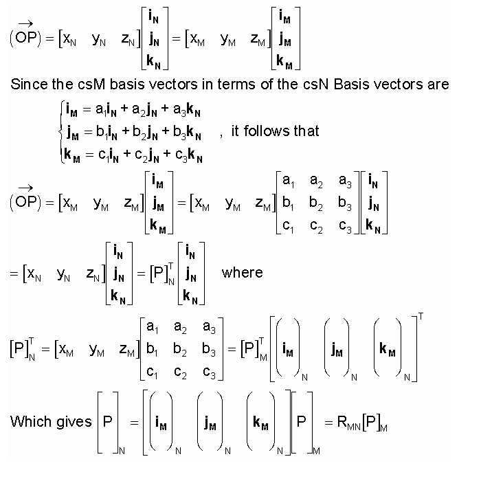
The elements of [iM]N are the csN
coordinates (a1,a2, a3) of csM's basis vector iM.
The elements of [jM]N and [kM]N
are taken similarly. The superscript T indicates the transpose of a matrix. We
name the matrix RMN as the Rotation Matrix which gives [P]N = RMN
[P]M = FMN( [P]M ) for a coordinate transformation
between systems that are rotationally misaligned but have the same origin. It can be shown
that RNM =RNM-1= RMNT for
this specific case. The -1 superscript denotes the inverse of the matrix.
The specific matrix elements a1,a2, a3, b1,b2,
b3, c1,c2, and c3 are derived as follows.
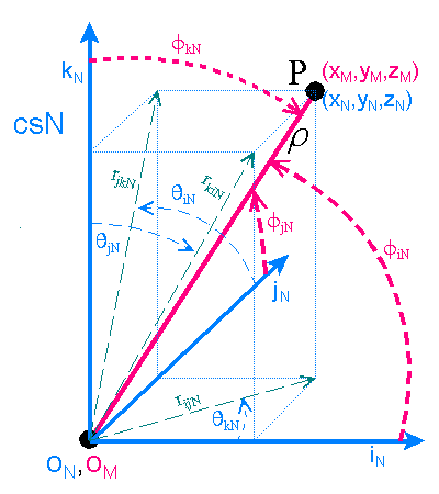
Let point P be on an axis of csM. The line between the origin and P we shall designate as r which also has length r. The
angle between r and iN, jN,
and kN we shall designate as fiN, fjN, and fkN ,
respectively. The f angles are measured with respect to the
positive direction of the associated axes. The projection of r
into the iNjN plane is designated rijN and has length rijN.
Similarly, rjkN and rkiN are projections of r
into the jNkN and kNiN planes respectively.
The angle about the iN (jN, kN)axis that the line rjkN
(rkiN, rijN) makes with respect to the jN (kN,
iN) axis we designate qiN (qjN, qkN). The q angles follow the right hand rule. That is, if you point the
thumb of your right hand in the positive direction of the iN axis, then your
fingers will curl in a positive qiN direction. Any
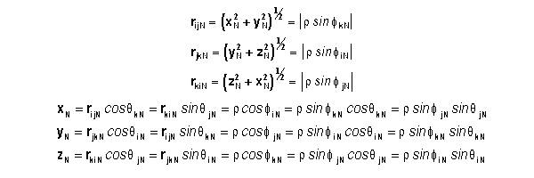
two angles which includes a q angle or three f angles is sufficient to describe a line's location in csN. The
angles for a given line are interrelated by the following identity
equations.
Now in our specific case, we let the vector from ON to P be equivalent to any
one of the basis vectors of csM (iM,
jM, or kM). This requires that r have a unit magnitude, giving
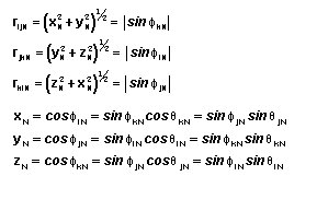
Using these relationships we may now determine representations by the following
relationships between corresponding basis vectors.

Combining these equations yields the following transformation.
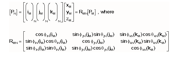
RMN is the rotational
transformation matrix which is used to transform the position P having the csM
coordinates [PM] into the csN coordinates [PN].
Small f's
Rotational Transformation
Suppose the f angles between the axes of csN and csM are
very small, such that
This can be rewritten as
 ,
,
where ekN(iM) is the
orientation angle of iM with respect to iN
about the kN axis. (the component of f in the iM
jM plane) Since iM, jM,
and kM are orthogonal (perpendicular), we can use their cross products to obtain the following identities and further
simplify the rotational matrix.

Which yields the following matrix. The e angle directions in
csN are determined by the right hand rule.

So that, for small angles,

where ekN is the small angle that the iM
and jM axes of are rotated about the kN axis with respect to
iN and jN etc.
Rotational Transformation for Small
Angles Between Only One Set of Corresponding Axes
For simplicity, we are going to describe all of the unit vectors of csM by their
relation to the kN axis of csN (using fN
and qN). The resulting transformation matrix is as
follows with PN=RMN[PM]

If the kM and kN axes are misaligned by small angles, but the
iM and jM axes are allowed to be misaligned by large angles from the
iN and jN axes, then the following approximations and identities can
be used to simplify RMN.

Substituting the above into RMN yields the following.

Substituting the es as defined in the previous section yields
the following.

Using the cross products jMNX kMN=iMN
and kMNX iMN=jMN we get substitutional
values for the cos(f) terms. This produces the following
approximation for RMN in terms of eiN, ejN, and qkN(iM).

Combined rotational and translational
transformation between non-aligned isometric rectilinear coordinate systems not having a
common origin
A function FMN() which transforms the coordinates of a system csM into the
coordinates of another system csN which is not aligned and has a different origin
can be developed using an intermediate coordinate system K (csK) which is aligned with csN
but has the origin of csM. First we transform the coordinates between csM and csK with
using the function FMK() , then transform the coordinates between csK and csN
using the function FKN(). The direct transformation between csM and
csN becomes
FMN([P]M) = FKN([P]K) = FKN(
FMK([P]M) ), where [P]M is the coordinate vector
representation of point P in csM. FMK([P]M)= RMK [P]M=
[P]K with RMK being the rotational transformation matrix
as described in the section on rotational transformation between
systems with common origin. FKN([P]K) = [P]K+ TKN
= [P]N with TNK being the translation matrix as described in the section on translation between aligned coordinate systems.
Combining the functions yields FMN([P]M) = RMK [P]M
+ TKN. Since csK and CsM share a common origin, TMN = TKN.
Since csK is by definition always aligned with csN, RMK can be replaced with RMN
provided we define RMN in this case as the rotational matrix between csN and
csM if one of the systems is translated without rotation so that they have common origins.
Now we can say FMN([P]M) = RMN [P]M
+ TMN.
Homogenous Transformation Matix (HTM) for
transformation between systems both rotationally and translationally distinct
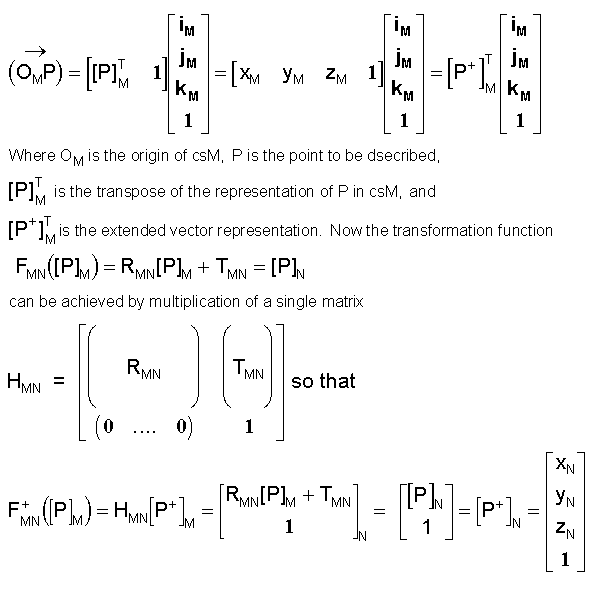
The function FMN([P]M) = RMN [P]M + TMN
can be reduced to a single matrix multiplication by extending by one dimension the
representation of the vector that locates the point P. Let P's representation in csM,
[P]M, with the coordinates xM, yM, zM,
be extended to a fourth dimension which has a constant value of 1. And let OM's
representation in csN, TMN also be extended to a fourth dimension which
has a constant value of 1. So we have
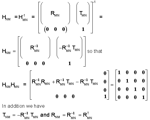
The matrix HNM which transforms point P's coordinates in csN into csM (given
RMN and TMN), is the inverse of HMN or HMN-1
= HNM and can be described by
Comments? contact Jim Miller (home page) or
jamiller@uncc.edu (e-mail)
Copyright 1998-2002 Jimmie Andrew Miller
Last update April 11, 2002
Disclaimer: The purpose of this document is instructional and
although we strive to eliminate mistakes it may contain errors which have not been
discovered. Additionally, it does not cover all possible formulations of related models.
 Consider the reference frame csN (to become coordinate system N) shown at the
right. The origin point is labeled as ON. P is the object for which we are
trying to define the location. The basis vectors are iN,
jN, and kN. The axes are iN,
jN and kN. The axis parallel to vector iN would be
called the iN axis etc.


 Assume we have
rectilinear non-aligned isometric systems, csN and csM, with common origins, ON
and OM, and we know the representation (of location) of point P in csM, [PM],
but we desire to determine its representation in csN, [PN]. By isometric, we
mean the length is the same for all basis vectors in csM and csN. By nonaligned we
mean that any of the iN, jN, or kN axes is not equivalent
to iM, jM, or kM axes, respectively. For example, iN
axis may run from southwest to northeast while the iM axis runs from south to
north. The diagram to the right illustrates our situation.


 ,
,


