Home |
 |
GeoDesign Tutorial 8 - Editing in ArcGIS Objectives:
Reference: Editing Tutorial, ESRI 2010, (esri.com accessed 03/25/2011) Load dataData can be found within the zip file ex8 by clicking HERE. Create a new folder on the Desktop. Name the folder edit, extract all the files here in the folder. You should see the following files in the folder:
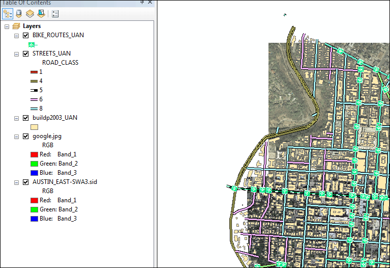
Creating new pointsIn this part of exercise, we will use the screen shot from Google Map (google.jpg, already geo-referenced) to create a number of new point features that represent bus stops around UT campus. You are introduced to the Editor toolbar, the Create Features window, and the Attributes window, which are the main elements of the ArcMap user interface when editing. Start ArcMap. If the Getting Started window opens, choose to browse for an existing map and navigate to your new folder edit then find ex12.mxd. Click the map and click Open. Inspect your map and see if you have all the layers: three feature classes, two raster grids.
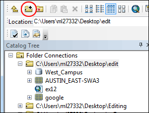
The task we are going to do first is to digitize bus stops from a Google Map screen shot. The features we are going to create are points. However, we do not currently have a layer contains points. We will first need to create a new feature class that will hold all the points we later create by referencing to the Google Map screen shot. We will do that using ArcCatalog. Open ArcCatalog from the Start-up menu. Make a connection to your folder edit. You should again see the file geodatabase and two raster grids.
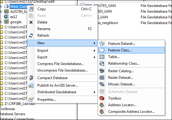
Right-click West_Campus file geodatabase, then choose New, and then click Feature Class..
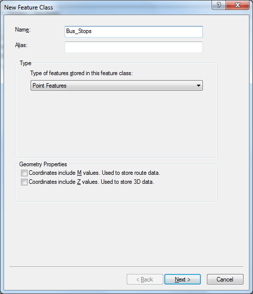
In the dialog window it appears, name your new Feature Class Bus_Stops, set Point Features as the type of features. You do not need to include M nor Z coordinates values. Click Next.
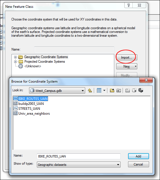
In the next dialog, click Import then browse to the folder and select one of the feature class in the file geodatabase and import the coordinate system from it. Click Next.
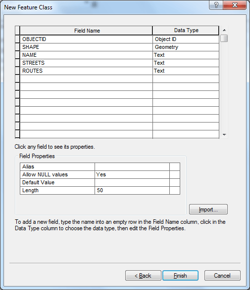
Use the default XY Tolerance, click Next. Also use the default Database Storage Configuration, click Next, In the final dialog window, we are going to create three new fields for this new Feature Class:
The data type for all three fields should be Text. Click Finish to complete the process.
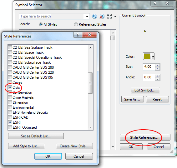
You should see the new feature class Bus_Stops is added to the file geodatabase. Now you can close ArcCatalog and return to ArcMap. Add the Bus_Stops layer to your map. If you want to add it from Catalog, you have to refresh the connection to the folder edit, then you will find the new Bus_Stops layer. Let's change the symbol for the layer. Click the symbol currently set for the Bus_Stops layer in the Table of Contents. In the Symbol Selector, click Style References... , then in the dialog window it appears scroll down, find and check Civic, Click OK to close the dialog.
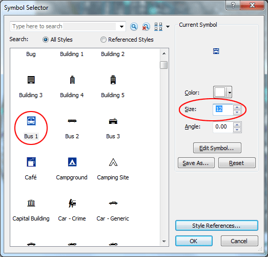
Back in the Symbol Selector, scroll down and find Bus 1 symbol, reduce its size to 12. Click OK to complete the process.
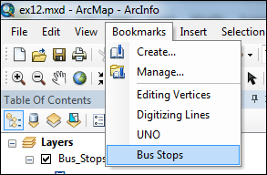
In the Table of Contents, turn off BIKE_ROUTES, buildp2003, and AUSTIN_EAST-SWA3.sid. We are going to add bus stops into the new layer by visually referencing to google map screen shot. Click the Bookmarks menu and click Bus Stops to zoom you to the area around Guadalupe St. between 21 and 24.
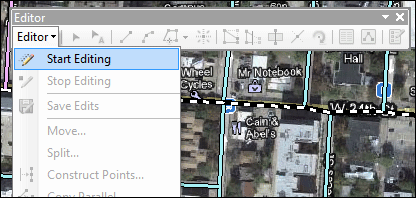
Click the Editor Toolbar button Click the Editor menu on the Editor toolbar and click Start Editing.
The Create Features window should appear on the right-hand size of the work place. We will first create a feature template for the Bus_Stops layer. Click Organize Templates button in the Create Features window.
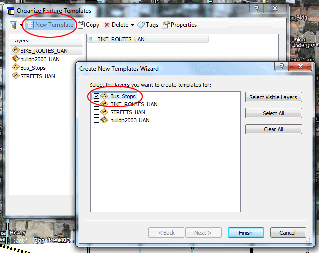
In the Organize Feature Templates dialog, click New Template, then in the Wizard dialog, check only Bus_Stops layer. Click Finish to close the Wizard.
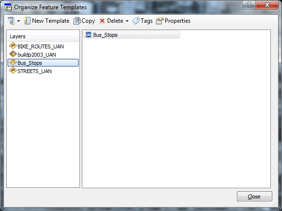
Back to the Organize Feature Templates dialog, click Bus_Stops layer, you should see a feature template with a Bus 1 symbol should appear in the box.
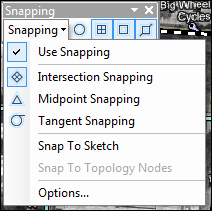
Click Close to complete the process. Now in the Create Features window, click the Bus_Stops point feature template. This sets up the editing environment so that you will be creating new point features in the Bus_Stops layer. We will place all the bus stops along the streets. We will turn the Snapping function on so that we can make sure we snap all the bus stops along the street line features. Add the Snapping toolbar to ArcMap. You can add a toolbar by clicking the Customize menu, pointing to Toolbars, then clicking the toolbar's name in the list. You can also add the Snapping toolbar by clicking the Editor menu, pointing to Snapping, the clicking Snapping Toolbar. On the Snapping toolbar, click the Snapping menu and confirm that Use Snapping is checked. If Use Snapping is not checked, click it to enable snapping.
Look on the Snapping toolbar and confirm that End , Vertex , and Edge snapping types are active.
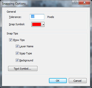
Click the Snapping menu and click Options. From this dialog box, you can specify settings for snapping in ArcMap. Make sure the Snap Tolerance is at least 10 pixels. (The snapping tolerance is the distance within which the pointer or a feature is snapped to another location) Also set the color for Snap Symbol to Red. Check the boxes for Show Tips, Layer Name, Snap Type, and Background. Click OK.
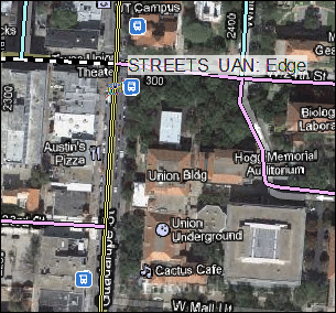
Using the google map screen shot, click the map to place a point directly over the bus stop near the intersection of Guadalupe and 24. Once again, place the bus stop right along the street, Guadalupe ST in this case. Move your pointer over the existing line representing Guadalupe ST and near the bus stop symbol on the google map screen shot in the map display, but do not click yet. Notice that the pointer icon changes to a square snap symbol and a SnapTip appears with the name of the layer (STREETS_UAN) and the snap type (Edge) in use.
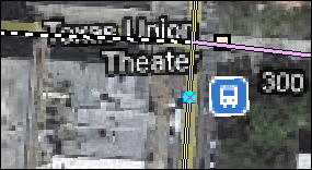
Click once to place the bus stop. Since you are creating points, clicking the map once adds the feature. Notice that the center of the symbol contains a solid, cyan-colored (light, bright blue) circle. By default, as soon as you create new features when editing, they are selected. This allows you to easily identify the new feature and add attribute values to it.
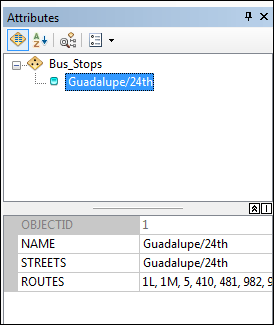
Click the Attributes button In the bottom of the Attributes window, Click inside the box for the NAME property value, which is currently <Null>. Type Guadalupe/24th and press ENTER. This action stores the attribute values for that feature. Click inside the box for the STREETS property value, which is currently <Null>. Type again Guadalupe/24th and press ENTER. Click inside the box for the ROUTES property value, which is currently <Null>. Type1L, 1M, 5, 410, 481, 982, 983, 987 and press ENTER. Now all the attribute values for that feature are stored.
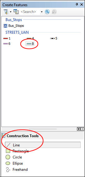
You can go ahead to add more bus stops by repeating these steps. Click Create Features button You have now completed the first task of this exercise and created new point features. Digitizing linesIn this part of tutorial, we will trace over the aerial photograph to create a new line representing a road. Because part of the road has already been created, you should use snapping to help ensure the new road feature connects to the existing roads. Again, on the Snapping toolbar, click the Snapping menu and confirm that Use Snapping is checked. In the Table of Contents, turn on AUSTIN_EAST-SWA3.sid layer. Navigate to the Digitizing Lines bookmark. You are now ready to begin digitizing the new road. In the Create Features window, click the ROAD_CLASS 8 line template, which is grouped under STREETS_UAN. The list of available construction tools at the bottom of the window changes to those used to create lines. Since the Line tool is the default tool for this template, it is activated automatically.
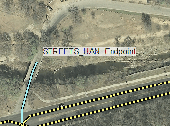
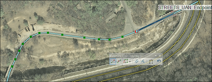
Move your pointer over the endpoint of the existing line in the western portion of the map display, but do not click yet. Notice that the pointer icon changes to a square snap symbol and a SnapTip appears with the name of the layer (STREETS_UAN) and the snap type (Endpoint) in use.
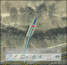
Now Click once. As you are digitizing, the Feature Construction toolbar appears near your pointer. It is a small, semitransparent toolbar that allows quick access to some of the most common tools and commands used when editing. If you find that the toolbar gets in the way of where you want to add a vertex, press the TAB key to reposition it.
Using the aerial photo as a guide, digitize the new line by clicking the map each place you want to add a vertex (green dot). Once you have digitized the new line, snap to the end of the existing feature and doube-click to finish the sketch and turn your shape into an actual feature in the geodatabase.
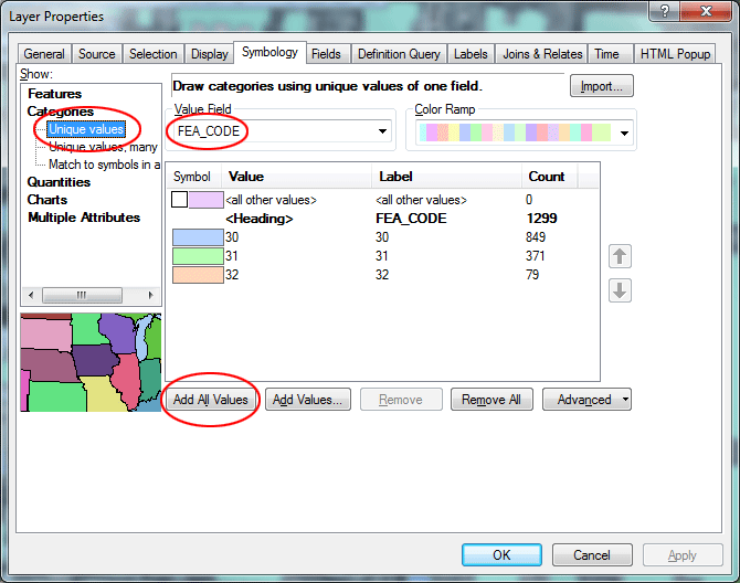
We have just added a new road to the STREETS_UAN layer. If you have attribute information available, you can click Attributes button and update fields in the Attributes window. Be sure to clear all selected feature by going to Selection menu then click Clear Selected Features. Creating new polygon featuresIn the Table of Contents, turn off google map screen shot and STREETS_UAN, and turn on buildp2003_UAN. Navigate to the UNO bookmark. We will first change symbology for the buildp2003_UAN layer. Double-click buildp2003_UAN layer. Set to use Unique value under Categories as the diaplay method. Choose FEA_CODE as the Value Field. Click Add All Values and un-check <all other values>. Click Apply and then OK to complete the process.
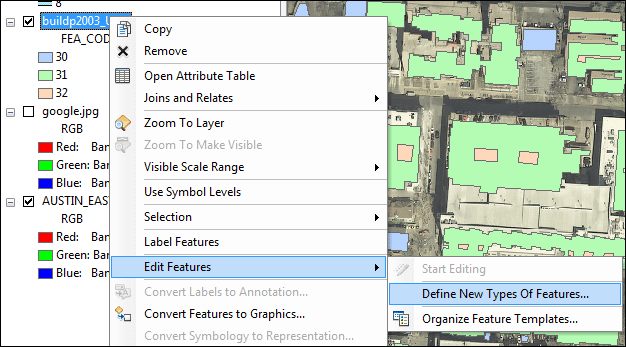
Defining new types of features to createSometimes you may want to create features of a certain type in an existing layer, but the layer is not set up to capture those features. ArcMap's Define New Feature Type wizard allows you to define new types of features making it easy to prepare your data to display and store the new types of features. The FEA_CODE field in the buildp2003_UAN layer specifies single family housing vs. non single family housing. But we want to be able to specify those newer constructions that follow the UNO design guidelines. We then will need to add a new category under the FEA_CODE field. Right-click the buildp2003_UAN layer in the Table of Contents, point to Edit Features, then click Define New Types Of Features. The Define New Feature Type wizard starts.
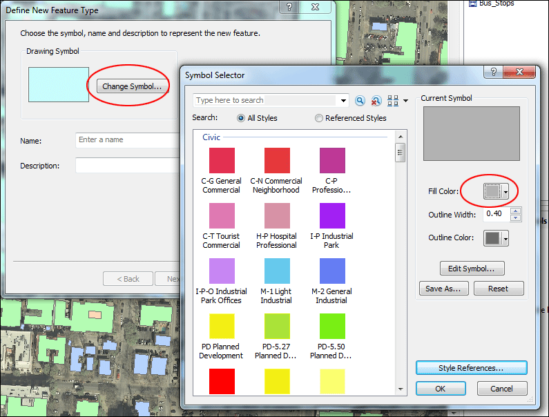
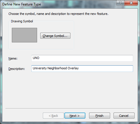
Click Change Symbol to choose a different symbol to be used for the new category. Click the Color drop-down arrow and click Gray 30% to change the fill color to gray. Click OK on the Symbol Selector dialog box.
Click in the Name box and type UNO. Click in the Description box and type University Neighborhood Overlay. Then click Next.
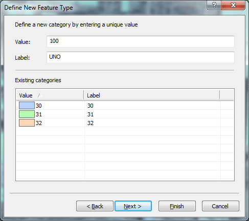
The next panel in the wizard shows you the existing categories in the layer. For Value, type 100 (just an arbitary number to distinguish from the existing values). Leave Label as UNO, which should be populated automatically from the name you set on the previous panel of the wizard.
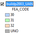
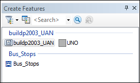
Click Next. The next panel in the wizard allows you to set the default attribute values that will be used for new features created with the new UNO feature template. Since we do not actually have any further information, click Finish to complete the process. A message appears that the new feature type was added successfully. Click No to quit adding new types. The new symbol appears in the layer's entry in the table of contents, and a new feature template has been created in the Create Features window.
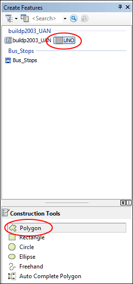
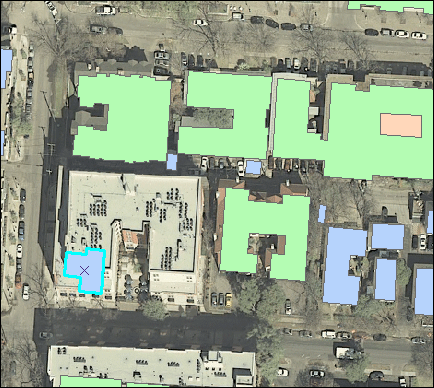
Now we are going to use this new template to create a number of polygons for those newer constructions under UNO guidelines. We will first use the aerial photo as a guide and digitize the building right around the center of this map view. Zoom in to take a closer look at the building by using the middle wheel button in the mouse. Click the UNO template in the Create Features window. Also make sure Polygon is selected as the construction tool in the bottom half of the window.
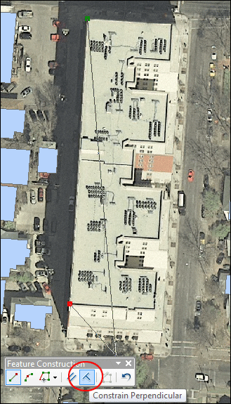
Starting from the top-left corner, click to place the first vertex. then click the bottom-left corner of the building roof and place the second vertex. Then in the Feature Construction toolbar, click Constrain Perpendicular button.
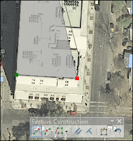
Then click the previous line segment, you can see the line flashes to confirm the selection. Then click the bottom-right corner of the roof top. You should realize that the new line is now constrained to be perpendicular to the previous line segment.
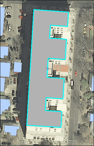
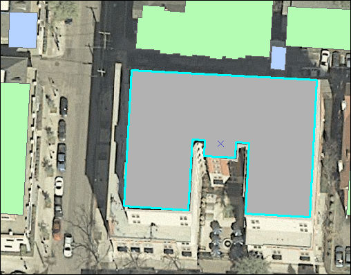
Repeat the same steps and keep using this Constrain Perpendicular function to outline the entire building roof top. Double-click the last vertex on the top-right corner to complete the process.
Use Pan tool Use Edit tool
With the polygon selected, press Delete key on the keyboard to delete it. Then click the UNO template again in the Create Features window, and follow the steps shown before and create a new polygon for this UNO building. (Polygon is the selected construction tool)
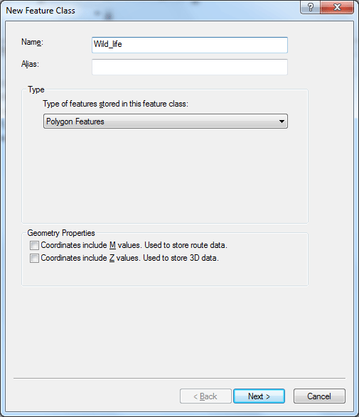
Now we have just added two new polygons for the newer UNO constructions. Be sure to clear all selected feature by going to Selection menu then click Clear Selected Features. Editing polygon featuresNavigate back to the Digitizing Lines bookmark. In the Table of Contents, turn off the buildp2003_UAN and turn on STREETS_UAN. Let's assume that City of Austin wants to designate a wild life refuge area near the Shoal Creek Trail. We are going to create a new polygon to specify the area. Before we do that, we have to use ArcCatalog to create a new feature class in the West_Campus file geodatabase for the wild life refuge area. Open ArcCatalog, connect to the edit folder then browse to the West_Campus file geodatabase. Right-click West_Campus file geodatabase, then choose New, and then click Feature Class.. In the dialog window it appears, name your new Feature Class Wild_life, set Polygon Features as the type of features. You do not need to include M nor Z coordinates values. Click Next.
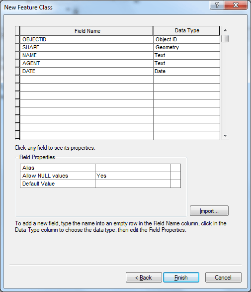
In the next dialog, click Import then browse to the folder and select one of the feature class in the file geodatabase and import the coordinate system from it. Click Next. Use the default XY Tolerance, click Next. Also use the default Database Storage Configuration, click Next, In the final dialog window, we are going to create three new fields for this new Feature Class:
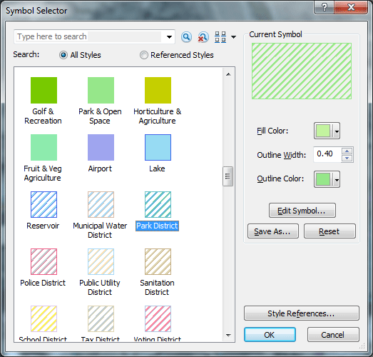
Click Finish to complete the process. You should see the new feature class Wild_life is added to the file geodatabase. Now you can close ArcCatalog and return to ArcMap. Add the Wild_life layer to your map. If you want to add it from Catalog, you have to refresh the connection to the folder edit, then you will find the new Wild_life layer. Let's change the symbol for the layer. Click the symbol currently set for the Bus_Stops layer in the Table of Contents. In the Symbol Selector, scroll down and find Park District symbol, click OK to complete the selection.
We will first create a feature template for the Wild_life layer. Click Organize Templates button in the Create Features window.
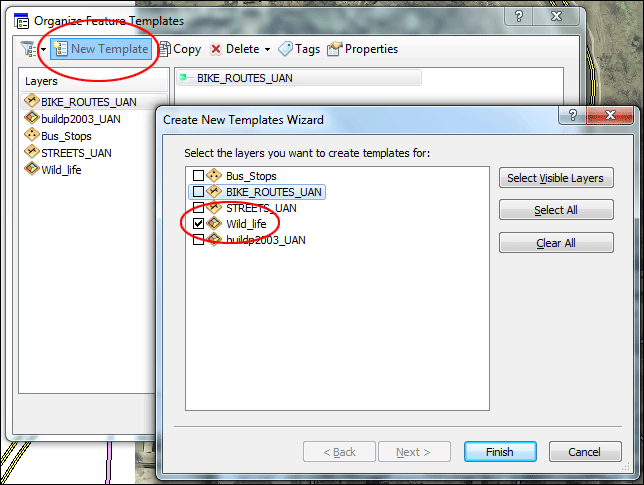
In the Organize Feature Templates dialog, click New Template, then in the Wizard dialog, check only Wild_life layer. Click Finish to close the Wizard.
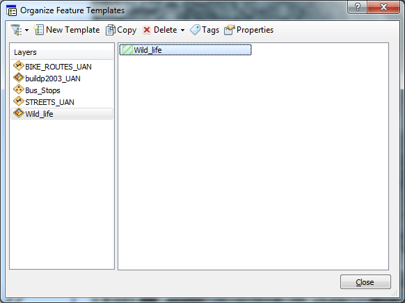
Back to the Organize Feature Templates dialog, click Wild_life layer, you should see a feature template with a Park District symbol should appear in the box.
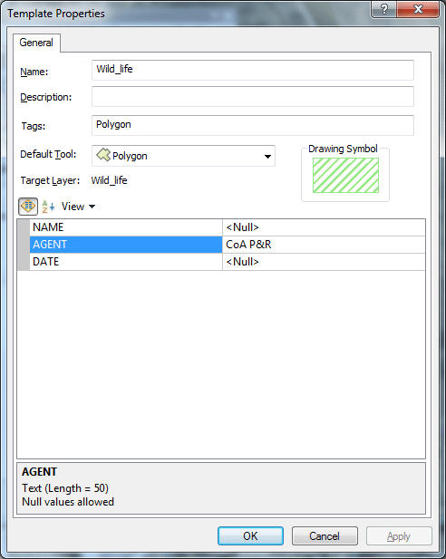
You can also pre-set some attributes for this particular template. Let's assume the agent in charge of all refuge areas is CoA P&R (City of Austin Park & Recreation). Double-click the template icon in the Organize Feature Templates dialog. In the dialog it appears, click inside the box for the AGENT property value, which is currently <Null>. Type CoA P&R and press ENTER.
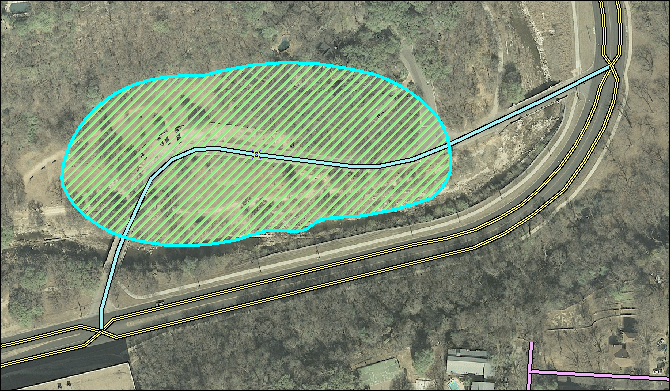
Click OK, Then close the Organize Feature Templates dialog. You should see the template for Wild_life layer is now in the Create Features window. Click the template for Wild_life layer in the Create Features window. Choose Freehand as the construction tool. Draw a polygon in the map as shown in the image below. You click one to start the drawing process, when about to form a loop, double-click to complete the process.
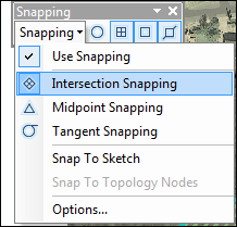
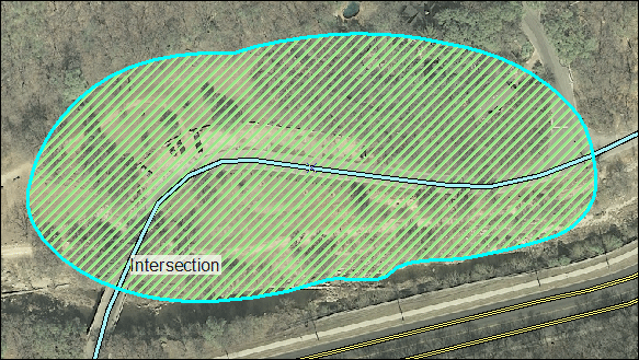
Cutting a polygonLet's say that the refuge area needs to be divided into two polygons based on the road that runs through the middle. You can use the Cut Polygons tool to split the polygon. To use the Cut Polygons tool, you need to select the polygon, then digitize a line where you want to cut the polygon. If you are cutting a polygon along a simple line, you can click to draw the line using the Straight Segment construction method. However, in this case, the road feature you want to use to cut with is long and curved, so it will be easier to trace around the road feature to create the cut line. Make sure the refuge area polygon is still highlighted. If not, use Edit tool on the Editor toolbar and click to select the polygon. Click the Snapping menu on the Snapping toolbar and click Intersection Snapping . This turns on snapping to intersections between features, which will help you ensure that the line used to cut the polygon starts and stops at the intersection of the polygon and line edges.
Click the Cut Polygons tool Click Trace tool on the Editor toolbar palette.
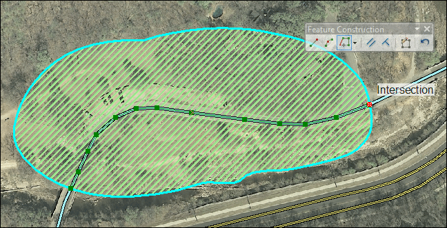
Snap to the intersection of the polygon edge and the road line to the left, then click to start tracing the line through the polygon. Follow along the road line to trace it.
Once you have traced all the way across the polygon, snap to the intersection of the polygon and line to the right, and click the map to place vertices.
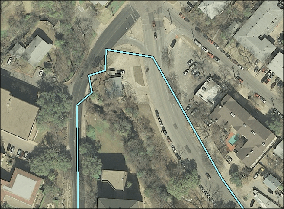
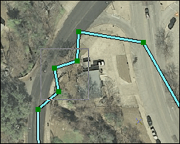
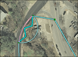
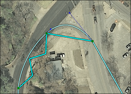
Right-click anywhere on the map and click Finish Sketch. Or you can click Finish Sketch botton on the Feature Construction toolbar. The polygons flash on the map as the cut is made and the new features are selected. Click the Edit tool on the Editor toolbar. Click each new feature and notice that you now have two polygons. Be sure to clear all selected feature by going to Selection menu then click Clear Selected Features. Editing vertices and segmentsIn this part of tutorial, we will be editing the vertices and segments that make up a feature. The Edit Vertices toolbar provides quick access to some of the most commonly used commands when editing vertices. Navigate to the Editing Vertices bookmark. You will see a poorly digitized street segment, we will drag the vertices and handles to edit its shape.
Click the Edit tool on the Editor toolbar and use it to select this street segment. Click the Edit Vertices button
Click the Delete Vertex tool
Click the Modify Sketch Vertices tool
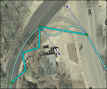
Use the Modify Sketch Vertices tool, Right-click the northernmost segment. point to Change Segment, then click Bézier. A new set of Bézier curve handles is added, and the segment changes into an S-shaped curve.
Drag the handles to reshape the curve to match the aerial photograph.
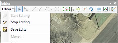
Click the map anywhere to update the changes you made to the shape. Click the Editor menu on the Editor toolbar and click Save Edits. Then Click the Editor menu on the Editor toolbar and click Stop Editing.
Close ArcMap if you are done working with the tutorial. The deliverable:
prepared by Ming-Chun Lee, 10/02/2014
|
|
