Home
GeoDesign
Tutorial 12 - SketchUP / Massing and Terrain
Basic SketchUp
SketchUp is a simple, powerful tool for creating, viewing, and modifying 3D ideas quickly and easily. It was designed to offer the spontaneity of hand drawing with the speed and flexibility of digital media.
The following information helps you learn SketchUp more effectively.
Video Tutorials
Video Tutorials is perhaps the best way to learn SketchUp, You can view them directly through the Help Menu: Menu Access: ( Help > View Tutorials ). Your computer will try to go online and access streaming versions of the tutorials from the SketchUp web site.
Or you can go directly to the webpage listed below to access those Video Tutorials:
http://sketchup.google.com/training/videos.html
Written Tutorials
A Google SketchUP user guides can be accessed HERE.
It is a 370-page PDF file.
Context Help
Clicking on the Context Help button (the big question mark) in the Standard Toolbar and then immediately clicking on any tool button, dialog box, or menu command will open the online reference material to the appropriate topic.
The Status Bar
The Status Bar is located at the bottom edge of the SketchUp Drawing window. The left side displays tips about each drawing tool as well as special functions which are accessible via modifier keys. This is a great way to discover advanced capabilities within each of SketchUp tools.
Menus
Many commands in SketchUp are accessible via both tool buttons, as well as by the pull-down menu system. Scanning through the menu system can give you a good overview of SketchUp's features.
User Interface

Drawing Window
The Drawing Window is where you create and visualize your model.
Title Bar
The Title Bar (at the top of the Drawing Window) contains the standard
Windows controls (close, minimize, and maximize) on the right, and the
name of the document open in the window. When you start SketchUp, a blank
Drawing Window will appear, with the name Untitled.
Menus
Menus appear below the title bar. The majority of SketchUp's tools, commands,
and settings are available through the menus.
Status Bar
The Status Bar is the long gray rectangular area at the bottom of the
Drawing window.
The left side of the Status Bar provides command prompts and SketchUp
status messages.
The right side of the status bar contains the Value Control Box
(VCB). The VCB displays dimensional information while you draw,
and can accept typed values as well.
The Value Control Box has two functions: The first is to dynamically display
dimensional information, such as length or radius, for an object as you
create or move it. The second is to override or re-specify the dimensions
of geometry or values of a command.
Toolbars
The Toolbars, which appear below the menus and along the left side of
the application, contain a user customizable set of tools and controls.
Standard Toolbar
The Standard Toolbar contains a variety of tools which help with file
and drawing management, as well as shortcuts to printing and help operations.
Drawing Toolbar
The buttons on the Drawing Toolbar activate the Line Tool, Rectangle Tool, Circle Tool, Arc Tool, Polygon Tool, Freehand Tool, .
- The Line Tool is used to draw single lines, multiple connected lines, or closed shapes. It may also be used to split faces or heal deleted faces.
- The Rectangle Tool draws rectangular faces, specified by clicking at two opposite corners of the desired shape.
- The Arc Tool is used to draw Arc entities, which are comprised of multiple connected straight line segments but can still be edited as an arc curve.
- The Circle Tool is used to draw Circle Entities.
- The Freehand Tool allows you to draw irregular, coplanar connected lines in the form of Polyline Curves or simpler Freehand Sketch Objects. These can be useful for representing contours or other organic shapes.
- The Polygon Tool draws regular Polygon Entities inscribed within a circle with anywhere between 3 to 100 sides.
Precision Line Drawing
While you are drawing lines, the Value Control Box (VCB)
at the bottom right corner of the SketchUp window displays the length
of the line in your current document units. To specify a new length, type
it in and tap the Enter key.
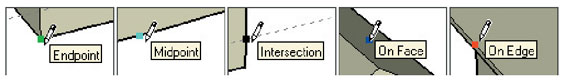
Drawing Lines by Inference
The Line Tool uses SketchUp's sophisticated geometric inference engine
to help you place your lines in 3D space. The assumptions it makes are
displayed in the Drawing Window as Inference Lines and Inference Points,
which show precise alignment between the line you are drawing and the
geometry of your model.
Construction Toolbar
Dimension Tool, Text Tool, Measure Tool, and Protractor Tool, Axes Tool, Section Plane Tool.
- The Dimension Tool is used to place Dimension Objects in your model.
- The Text Tool is used to insert Text Objects into your model.
- The Tape Measure Tool performs a number of dimension-related operations. These include measuring the distance between two points, creating Construction Lines, and re-scaling an entire model to an exact dimension.
- The Protractor Tool allows you to measure angles and create Construction Lines.
- The Axes Tool is used to move, or reorient, the drawing axes within your model.
- The Section Plane Tool is used to create Section Cut Effects within your models using Section Plane entities and section slices.
Edit Toolbar
The Edit Toolbar contains geometry modification tools.
- The Offset Tool creates copies of co-planar lines and faces that are a uniform distance from the originals. You can offset edges of faces either inside the original face, or outside of it.
- The Push/Pull Tool is used to distort and re-proportion faces of your model. Depending on the nature of geometry you use it on, it will displace, extrude, re-attach, and/or subtract faces. It is valuable both as a massing exploration tool and as a precise construction tool.
- The Move/Copy Tool allows you to move, stretch and copy geometry. It can also be used to rotate Components.
- Use the Rotate Tool to rotate drawing elements as well as single or multiple objects within a single rotation plane. Also, by selecting only a portion of an object, the Rotate Tool can be used to stretch and distort geometry.
- The Scale Tool allows you to resize and stretch selected geometry relative to other elements in your SketchUp model.
- The Follow Me Tool is used to extrude faces along a path such as an edge or line drawn with the freehand pencil.
Principal Toolbar
Principal tools are those tools that tend to be used most often in SketchUp.
- The Select Tool allows you to specify which drawing entities to work with when using other tools or commands.
- The Paint Bucket Tool is used to assign Materials (colors and/or textures) to entities in your model. You can use it to paint individual elements, fill a number of connected faces, or replace a material with another throughout your model.
- The Eraser Tool is used primarily to delete edges, Construction Lines, and objects from the Drawing Window.
Selecting Single Entities
Use Select Tool and Click on the entity. The selected element or object
becomes highlighted in yellow.
Window and Crossing Selections
Window selection / Crossing selection
You can use the Select Tool to drag a rectangular window to quickly
select multiple elements
Please note that a rectangle drawn from left to right (Window
selection) will select only drawing elements or objects fully
contained within the selection window. Alternatively, a selection rectangle
drawn from right to left (Crossing selection) will select
any drawing elements or objects within the rectangle as well as any that
are only partially within the rectangle.
You can also select with greater flexibility by using the Control and Shift modifier keys:
- When you hold down the Control key, the Select Tool becomes additive, and only adds to the selection set.
- By holding down Control and Shift
simultaneously, you make the Select Tool subtractive, which
means it
will only remove geometry from the selection set.
Making and Editing Groups
Once you have created a selection set, you may want to preserve it for
quick re-selection in the future by creating a Group. ( Edit >
Group ) Once a group is defined, the elements within it become
encapsulated so that selecting one will instantly select the entire group
instead. This is a great way to speed selection of things like cars or
trees.
Another advantage is that elements within a group become isolated from elements outside it so that they cannot be directly altered. The Explode command ( Edit > Group > Explode ) returns geometry back to normal edges and faces.
Stretching Geometry
When you move an element that is interconnected with others using the
Move Tool, SketchUp will stretch geometry as necessary.
You can move points, edges, and faces in this manner.
Repeating a Push/Pull Operation
Once you have performed a Push/Pull operation, you can
have SketchUp automatically apply another Push/Pull of the same amount
by double-clicking.
Camera and Walk (Walkthrough) Toolbar
The buttons on these two Toolbars activate Viewing Tools such as the Orbit Tool, Pan Tool, Look Around Tool, Walk Tool, Zoom Tool, Zoom Window Tool, Zoom Extents Tool, and the Undo View Change Tool.
- The Orbit Tool rotates the camera about the model. This is most useful when viewing an object from the outside.
- The Pan Tool moves the camera vertically and horizontally along the picture plane.
- The Zoom Tool allows you to interactively zoom in and out of your current view, moving back and forth in a sense.
- The Zoom Window Tool allows you to select a rectangular region to enlarge to fill your window.
- The Zoom Extents Tool zooms your view to a distance which makes the whole model visible, and centers it in the drawing window.
- The Previous Tool allows you to return to the last view of your model.
- The Look Around Tool pivots the camera around a stationary point at the point of view. This is like standing still while turning your head to look around. You can look up and down as well as side to side.
- The Walk Tool allows you to maneuver through your SketchUp model as if you were walking. Specifically, the Walk Tool fixes the point of view to a particular height, and then allows you to steer it around your model. The Walk Tool is available only when Perspective is enabled.
- The Position Camera Tool is used to position the camera at a certain eye height such that you can check the line of sight of a model or walk through the model.
Viewing Your Model
SketchUp offers many viewing operation shortcuts:
First, a three-button scroll wheel mouse is key. The three most often
used view tools : Orbit, Zoom, and
Pan, are accessible via the middle mouse scroll wheel at any time.
- To Orbit: Press down on the wheel as you would a button and move the mouse.
- To Zoom: Scroll the wheel up and down.
- To Pan: Press down on the wheel and hold down the Shift key.
Using these methods is many times faster than clicking back and forth between view tool buttons on the Toolbar.
Display Modes Toolbar
The buttons on the Display Modes Toolbar are shortcuts to SketchUP's Display
Options, including
wireframe, hidden line, shaded, shaded with textures, and X-ray transparency.
Views Toolbar
The buttons on the Views Toolbar are shortcuts to SketchUp'¡¦s
Standard View Presets.
Layers Dialog Window
The Layers Dialog Window provides quick access to several often used layer
operations: (Window > Layers)
- Display the Current Layer
- See What Layer an Entity is On
- Change the Layer Assignment of Entities.
- Bring up the Layers Manager.
Layers
In SketchUp, a layer is not so much a dimensional space as it is an attribute
of geometry. Elements and objects on different layers remain fully interconnected
with one another. This makes SketchUp layers useful primarily for visibility
management, rather than as an organizational container.
Fortunately, Groups and Components DO encapsulate and separate geometry in a way that is congruent with other layer systems. You can achieve the same kind of layer behavior you may be accustomed to by first making groups or components BEFORE placing elements on different layers.
Shadow Settings Dialog Window
The Shadow Settings offers a compact way to control shadows. It includes
a button to launch the full Sunlight and Shadows Options dialog box, a
button to enable/disable shadows, and controls for setting the time of
year and time of day. (Window > Shadow Settings)
Components
Components can be listed in, and inserted from, the Component Browser. To open the Browser, select Components from the Window Menu. ( Window > Components )
The Component Browser gives you access to the contents of SketchUp's Component Library, which includes a variety of pre-built Components that you may find useful in your models. You can select from the available libraries by selecting them from the list box at the top of the dialog box.
Inserting a Component
To insert a Component from the browser, click on its name and then click
in the Drawing Window.
Components can also be loaded into a drawing by dragging and dropping
files with .SKP extension into your drawing window or
by using the ( File > Insert > Component ) menu
command.
Sandbox tools
Sandbox tools are those tools used to create and manipulate large surfaces (TINs) in your models. These tools include the Sandbox From Scratch Tool, Sandbox From Contours Tool, Smoove Tool, Stamp Tool, and Drape Tool.
Enabling the Sandbox Tools
The sandbox tools do not appear in SketchUp by default, but can easily
be enabled using the Extensions Manager (the Extensions panel of the Preferences
dialog box). To enable the sandbox tools:
- Open the Extensions Manager (Window > Preferences > Extensions)
- Click the check box next to the extension that you want to enable.
- Click Ok
The short introduction provided above is meant to give you some
quick reference and allow you to have a quick overview on the program.
However, as mentioned before, more help is available online, including
video tutorials and User Guides. We strongly suggest that, before proceeding
to the exercise, you go to watch some of the video clips available online,
Tutorial 12
The goal for this part of tutorial is to complete converting GIS to SketchUp and building a massing/terrain model for your site.
Getting GIS layers ready
Before you can proceed to export GIS maps to SketchUp, you have to have your basemap for the study area ready, which contains all the data layers you need for only your project site.
For your project, you will need the following layers:
- Building Footprints (if your site is in Austin, then you can get this layer buildp_2003, from City of Austin GIS data sets)
- Street Curb Lines (for Austin, please get this layer from HERE)
- 1997 2 FT Contours (contour from City of Austin GIS data sets)
Then you will have to create a new polygon layer to specify your project area.
Please now open ArcCatalog.
First off, connect to your folder by clicking "Connect to Folder" button. Browse to find you folder.
In the catalog tree, please find your folder, then right-click the folder icon, then in the menu, please click New, then select Shapefile...
In the dialog, name this new layer "project_site", choose "polygon" as the feature type, then you will have to define a coordinate system for this layer. Click Edit.. button as shown below:
Then in the next dialog, click Import... as we are going to get a coordinate system from an existing layer (either buildp or contour).
Browse to find a layer (either buildp or contour), then click Add to import the coordinate system. You then should be able to see all the coordinate system information. Click OK twice to complete the process. Now you have your new layer ready, but now it is just an empty layer. You will later use ArcMap to build your site polygon.
Now open ArcMap, first add buildings, contours, and curbs into a blank map, then add the empty shapefile at the very end. Then make only curbs and empty shapefile on, turn the other two layers off.
CREATING FEATURS by EDITING
You are going to create a polygon in the empty shapefile to specify your project area. You do so by "editing" this empty shapefile.
First, you have to add the editing toolbar into ArcMap. To add the Editor toolbar, Click the Editor Toolbar button on the ArcMap Standard toolbar to display the Editor toolbar. Then you may want to Click the toolbar's title bar and drag it to the top of the ArcMap application window, make it docked.
You can also add the Editor toolbar from the Tools menu. Click Tools and click Editor Toolbar. Or you can add it by clicking the View menu, clicking Toolbars, then checking Editor.
Something about Editing
All editing takes place within an edit session. The edits you make are immediately visible on your map but are not saved to the database until you choose to do so.
How to start and stop an edit session
To Start an edit session, Click the Editor menu in the
Editor Toolbar, and click Start Editing. The Editor toolbar
is now active.
To Save your edits in the middle of an edit session, Click the Editor
menu, then Click Save Edits. Any edits you have made
are saved to the database.
To Stop an edit session completely, Click the Editor menu and click Stop
Editing, then Click Yes to save changes, Click No to quit without
saving.

Task
There are several tasks you can perform during an edit session, but in your case, you will have to choose: Create New Feature.
The target layer
When you're creating a new feature, the target layer determines the layer where a new feature will stored. The Target Layer dropdown list (shown below) contains the names of all the layers in the datasets with which you're working. You must set the target layer whenever you create new features.
In this case, look for your project_site layer and set it as the target.

Creating new features
You can create three main types of features with the Editor toolbar: points, lines, and polygons, depending on the type of features in the target data layer.
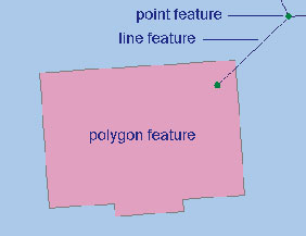
In your case, you will have to create a polygon to specify your study area. To create a polygon, you must first create a sketch. A sketch is composed of all the vertices and segments of the feature. Vertices are the points at which the sketch changes direction, such as corners; segments are the lines that connect the vertices.
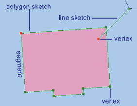
You can create a sketch by creating the vertices and segments that make up the features. Vertices are marked in green, with the last vertex added marked in red. The Sketch tool is the tool you will use most often to create a sketch.

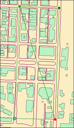
More specifically, you use Sketch tool and click to place the green marks, which will eventually enclose a polygon, you double-click to place the last mark to finish sketching (you do NOT have to go back to the starting mark, only need FOUR marks to complete a Rectangle). Then you will see a new polygon has been created in your target layer. Stop this edit session and save your editing.
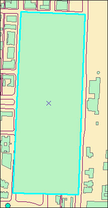
Now you have a layer that specifies your project area.
CLIPPING FEATURES
Sometimes the acquired data sets cover a greater area than the user is interested in. For example, all the layers you have downloaded are for the entire Austin area, but you are only interested in what is in your site.
The data set can be clipped to the area of interest by using features in one layer to clip the features in another layers. To do so, you will have to know about ArcToolbox.
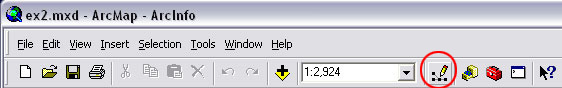
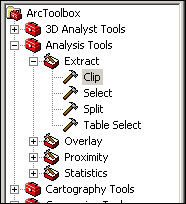
ArcToolbox is the application that provides an environment for performing geographic information system (GIS) analysis. ArcToolbox allows the user to perform a variety of geoprocessing tasks including data conversion. To access ArcToolbox, click on the ArcToolbox icon in ArcMap.
![]()
To clip one layer based on another, the user must use Clip found in the Extract portion of Analysis Tools in ArcToolbox.
Now, for completing your exercise, you will have to clip all these layers: Bldg footprints, Curbs, and Contours.
In the Clip dialogue box, you choose, each time, one of the Three layers as the Input Features, and choose the project_site layer as the Clip Features, and name your output layer (output feature class, be sure to save as a shapefile), or just use default name, then you click OK to finish clipping. You will see that the output layer will be added into your map.
OK, now I assume that you all have done clipping and have a base map for your site. Let's move on.
For the in-class demo, please click HERE to download all the files and put them in a folder, so you can follow the instructions step by step.
However, for your own assignment, you have to follow the steps listed above to prepare the base map for your own project.
GIS and SketchUp
OK, now let us get started to convert your GIS base map into a SketchUp model. But First, you have to make sure the ArcGIS plug-in has already installed in ArcMap. If so, you should be able to see an icon in the main toolbar when you open ArcMap.
If not, then first go to View > Toolbars, then check "SketchUp 6 Tools".
If still not see the icon, please go to Sketchup.com to download the
plug-in, they provide an instruction showing you how to install it.
http://sketchup.google.com/download/plugins.html
OK, with ArcMap opened, now you can add the layers needed for 3-D modeling,
you may need the following layers:
1. Building footprints - for buildings, of course
2. Contours - for building the terrain model
3. Street curb edges - for showing the streets
4. The area boundary - for geographic reference
Look at the attribute tables and identify which field specifies building heights in the Building footprints layer? which one is for elevations in Contours layer?
Now use "Select Features" tool to select everything that you would like to bring in to SketchUp (you can use the tool to make a selection window that can contain everything on the map), make sure everything has been highlighted then click the GIS plug-in icon.
An Options window pops up, and you can set the options and tell SketchUp how to model your project. Set options for the following layers, for Building layer, check "Extrude by field", then choose "Elevation" as the value. For Contours, check "Elevate by field" and choose "Elevation". Hit Browse to locate your folder and give it a name meaningful to you. Click OK when you are done. SketchUp will launch automatically with all the models built for you.
Now it's SketchUp time.. you can now save your GIS map and
close ArcMap.
Then switch to SketchUp, First, click "Zoom
Extents" tool and then you should see the whole model, including
buildings, contours, and the street edges.
Layers
Using Layers is very useful; Layers help you organize your model.
To turn on Layers dialog window, go to Window > Layers.
In the window, you can see all the GIS layers already there. Layer
0 is default, but nothing in there.
Terrain Modeling
Now we are going to build terrain model using contours. Make contours
layer the active layer and make the rest of layers invisible.
The tool we are going to use is called "Sandbox", it is actually an extension, if you don't see the sandbox toolbar, then go to Window > Preferences , then click Extension and check Sandbox Tools.
![]()
Now with only the contours shown on the screen, use "Select" tool to select all the contours. (make a select window to cover all the contours)
Group / Ungroup (Explode)
Each single contour now is a group, we have to explode (ungroup) all the
groups before you can use them to build the terrain. With all the contours
(groups) selected, go to Edit, then all the way down
to the bottom of the menu, then click Explode.
Then in Layers, create a new layer by clicking the PLUS sign, name the new layer "terrain", also make this new layer the active layer by checking the round check box on its left side. Make both contour and terrain layers visible.
Now select all the contours again, then hit "From Contours" icon in the Sandbox toolbar to build the terrain model.
![]()
It may take a while.....
After the process is done, first make contour layer invisible. you then can paint the terrain model using a different color if you like. Click Paint Bucket tool (next to Select tool), in Materials window, select Colors in the drop-down menu, then pick a color you like to paint the terrain.
Street Pavement
The next step, is to make all the street curb lines marked onto the terrain, the Drape tool in the Sandbox toolbar is the one we are going to use.
![]()
Make the curbs layer active and the only one visible
Use Select tool to select all the street edges, again, you have to explode all the groups (File > Group > Explode), then with all the curb lines selected, make all the lines a group (File > Make Group). Then with the group still selected (highlighted) use Move/Copy tool to move entire curbs group up, completely above the terrain model (You may later make the terrain model visible after moving the street edges to make sure all the curb lines are above the terrain). After you are done moving the cur blines, use Select tool and click on any "blank" area to clear selection.
When you are moving a model, make sure you are on the correct direction, you can pay attention to the inference message SketchUp provides to you. For example, make sure you are on Blue Axis when moving the pavement group up.
Now, first make sure you are not selecting anything (click any blank area), then make the terrain layer the active layer, (because we want to mark all the street lines on the terrain), then click "Drape" tool, then click first on the "Street edges Group" (wait until computer responded), then click on the "Terrain Group" (wait until computer responded). It may take a while to process the draping (depends on how big your area is, sometimes it may takes hours to process).
When the drapping is done, hide the street edges layer (make it invisible), and make sure you are still on terrain layer.
You may want to paint streets using a different color, but before you can do that, you have to select all the terrain (using Select tool) then right-click the mouse, in the menu, select Edit Group, this will allow you to access the original terrain group.
then you can paint all the street surfaces in a different color (Paint Bucket tool).
After everything is done, just click any blank area to close the Edit-group session.
Bring on Buildings
Just make the building layer visible, then you can see everything. You may now apply different colors to buildings in terms of their uses.
To cut the bottom portions of all the buildings out (below the terrain), you first make only buildings visible, then select all the buildings and explode them. Then turn the terrain on, and make sure buildings is the active layer. Select everything, including all the buildings and the terrain. Then place the cursor over any building, right-click, in the menu, click Intersect, then Intersect with Model. You will have to again wait for a while allow SketchUp to Process.
After the process is completed, use select tool to drag a window "from right to left", this will allow you to select all the bottom portions of the buildings.
With all the bottom portions selected, just hit the delete key on the keyboard to get rid of them.
prepared by Ming-Chun Lee, 10/10/2014