Home |
 |
GeoDesign Tutorial 9 - Geo-referencing (registering a photo) Objectives:
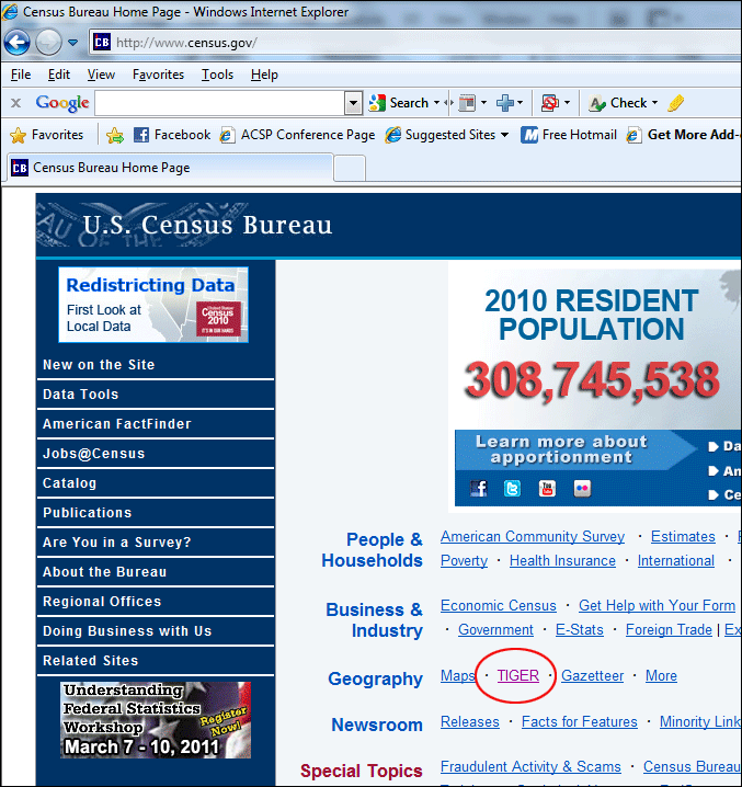
Background and DefinitionsRaster data can come in a variety of formats but is commonly obtained by scanning maps or collecting aerial photographs and satellite images. Scanned maps don't usually contain information as to where the area represented on the map fits on the surface of the earth; the locational information delivered with aerial photos and satellite imagery is often inadequate to perform analysis or display in proper alignment with other data. Thus, in order to use this type of raster data in conjunction with your other spatial data, you often need to align—or georeference—it to a map coordinate system. In this exercise, you will learn how to register an orthophoto to a street map. You will do this by adding links between control points on the photo and the corresponding street map. This process is known as georeferencing, assigning coordinates from a known reference system, such as latitude/longitude, UTM, or State Plane, to the page coordinates of a raster (image) or a planar map. Georeferencing raster data allows it to be viewed, queried, and analyzed with other geographic data. ArcMap requires a minimum of three links to transform the photo by rotating, scaling and warping it as needed to fully register or align it to the street map. In many instances, three links are adequate to georeference an image. However, more links can be added as necessary (up to 60) to obtain a better alignment. The residual is a measure of the actual location of the map coordinate to the transformed position in the raster. An RMS error describes the deviation between the reference points in the street map and the values calculated by the transformation. Optimally the difference between the calculated x,y coordinate value and the true x,y coordinate value should be minimized. In order to calculate an RMS error you must have at least three points, with less points you will get an incorrect RMS error of 0.00. This is different from a ‘perfect’ fit, which would hypothetically create a zero error. To visualize how the computer measures the RMS error, think or an elastic sheet which you are trying to pin onto a flat board. If you stretch the rubber beyond just turning and expanding you will get ‘stretch marks’ or lines that run between the pins. These are artificial compensations that the rubber allows you to make (because of its flexibility). Similarly when georeferencing a map you can stretch the map artificially, but this alters the true relationships between points. Every time you stretch the map in this way it increases the RMS error. You will now try to fit an image and add more points in order to minimize the RMS error. SetupData can be found within a zip file, which can be downloaded here. Extract the file into your personal space. When you extract this zip file you should notice it has only one image file: ut.jpg. It was obtained by taking a screen shot out of Google Earth. This image has not yet been geo-referenced, contains no coordinates information. Setting up an Address LocatorUS Census Bureau provide a lot of useful GIS data on their website: http://www.census.gov/. For this exercise, we will download a street layer and use it to create an address locator for address mapping (geocoding). Go to www.census.gov. On the main page, click TIGER under the Geography category.
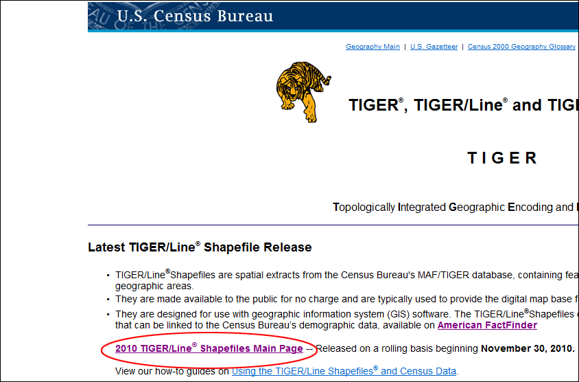
On the next page, which is the gateway to the most current census shapefiles, select 2010 TIGER/Line® Shapefiles Main Page.
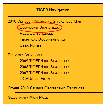
Then on the next page, select Download Shapefiles on left in the orange TIGER Navigation panel.
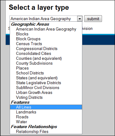
In the Select a layer type drop-down menu, choose Features > All lines, then click Submit. Note: This file primarily contains all the streets in an area. However, also include other linear edges such as waterbodies, railroads, and trolleys. For geocoding and network analysis, All lines is the one you will have to choose.
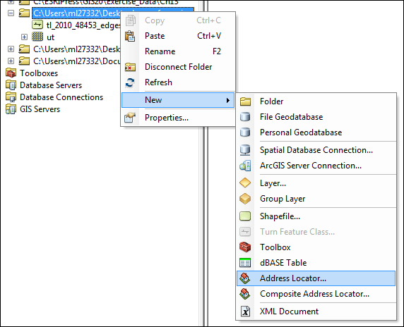
Then select Texas and Travis County, click Download to get the zip file. Open it and extract the files into your personal space. Now please open ArcCatalog. Make a connection to the folder that contains both the image file and the line shapefile. Once you connect to the folder, right-click on the folder name, select New > Address Locator...
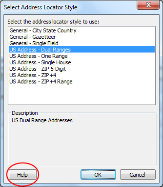
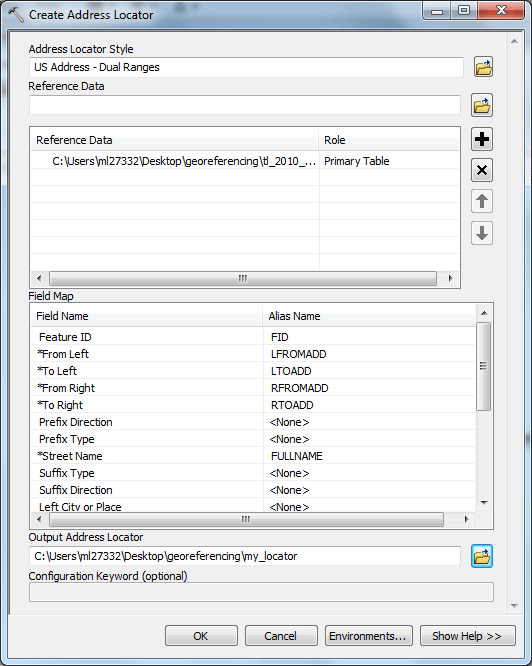
In the dialog window, in the first field "Address Locator Style," click the Browse Folder icon
A warning message will show up at the top in yellow, ignore it, we will fix that later in the next few steps.
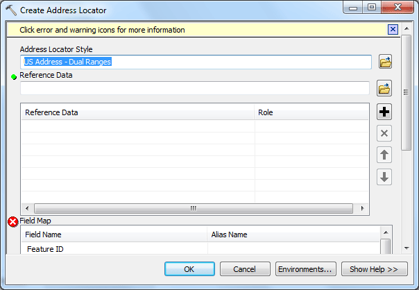
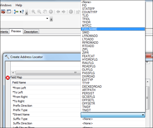
In the next field "Reference Data" click the Browse Folder icon and navigate to your folder and select the shapefile you got from census.gov: tl_2010_48453_edges.shp. Here you will see another red circle indicating another error, don't worry, you will fix this too in the next step. Scroll down to find the Field Map, in the field named "Alias Name," find the field "Street Name," now it shows "<None>" you have to click <None> and change it to FULLNAME.
Now the error message should disappear. Scroll down to the last field "Output Address Locator" on the bottom of the dialog window, click the Browse Folder icon and make sure you are still in your folder. Give it the name my_locator. Your address locator settings should look like the screenshot below. Click OK to set the locator.
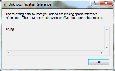
It may take a few seconds to process the address locator. Once it is done, you should see a little red house icon Now you can close ArcCatalog. Then go ahead to open ArcMap. Add the shapefile tl_2010_48453_edges.shp to your map content. Note: add the shapefile before you add the image file. Then add the image file ut.jpg. When you see a message warns you of Unknown Spatial Reference, just click OK.
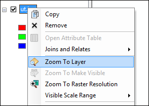
The image should be added to the table of contents, but still not visible in the content window yet. To view it, right-click the image layer name in the table of contents, select Zoom to Layer.
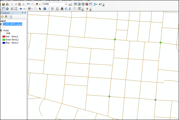
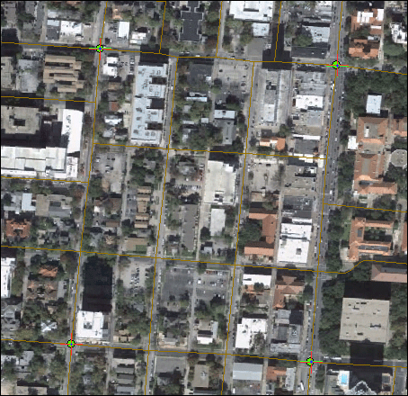
Right now the image has no spatial reference, so ArcMap does not know where to put it in relation to the shapefile. We will fix this problem in the next few steps. We are going to identify at least three points (the more the better, four in this exercise) on the image that will serve like anchor points for georeferences. The following four intersections have been identified as our reference points:
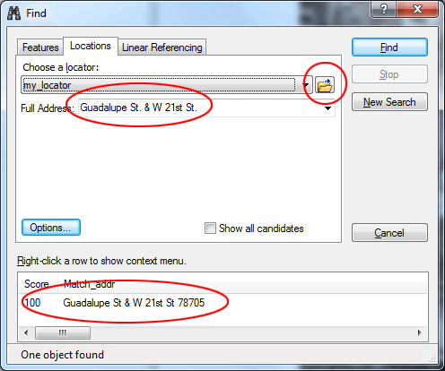
Now the next step is finding these four intersections on the streets shapefiles ( tl_2010_48453_edges.shp ). Right-click the streets layer name in the table of contents, select Zoom to Layer. Then in ArcMap, Click on the Find tool Select Locations tab. Click the Browse Folder icon next to Choose a locator field and navigate to find the locator my_locator you created earlier. In the Full Address: box, type Guadalupe St. & W 21st St. Note: three default intersections connectors are & | @. Click Find, you should see the result in a few seconds. For this case, only one is identidied, and it is a correct one. Usually the first address given is the best match.
Notice that the spot on the map flashes. Right-click the first matched address and select Add Point from the menu. This will place a green point at that intersection. Repeat the same steps with the other three intersections. After you find all four intersections, use Magnifying tool
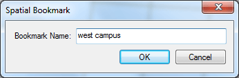
Now go to Bookmarks menu, click Create... name your bookmark "west campus" This bookmark will allow you to quickly navigate back to this exactly location in the streets layer.
Right-click the image layer name ut.jpg in the table of contents, select Zoom to Layer. Click the Customize menu, point to Toolbars, and select Georeferencing. This brings up the Georeferencing toolbar.
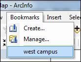
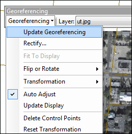
Since we only have one raster image, so ut.jpg should automatically show in the Layer drop-down box. Click the Georeferencing drop-down arrow and select Fit To Display from the drop-down menu. ArcMap scales the images to fit in the current window. Click Windows menu and then Magnifier. A small window appears with a default magnification of 400 percent. When you drag the window and release the mouse button, it magnifies the portion of the display it is currently on top of (notice the cross hair and circle moving on your map) by 400 percent. This establishes your viewing area. Adding linksLinks are created by identifying an image location, then specifying its corresponding real-world or map coordinate location using control points. Obtain the map coordinate value by locating a point on a shapefile (streets in this case) that corresponds to the image location, or by explicitly entering an x,y coordinate pair. NOTE When adding links, remember to click a location on the image first, then a corresponding location on the reference data set. Drag and center the magnifier window over to the upper right hand corner where you can see the intersection of Guadalupe St & 24th St. Click the Add Control Points button Now go to Bookmarks menu and click the bookmark west campus you made before.
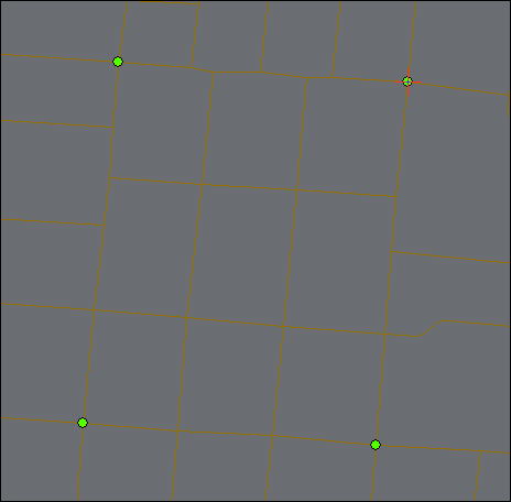
Center the same intersection on the streets shapefile layer. A red control point will be added. You’ve just established the first link between your two layers.
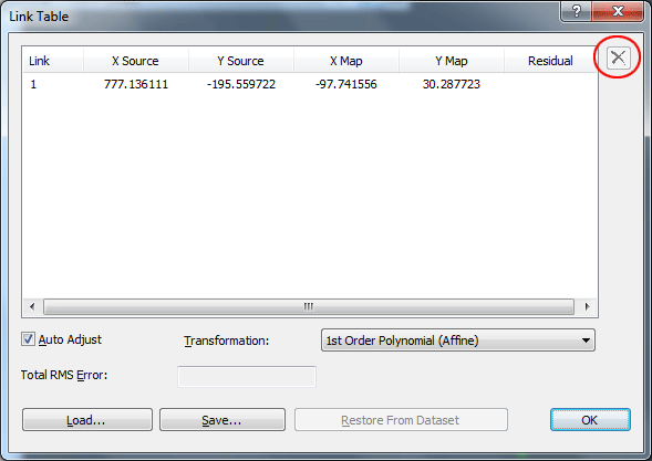
Notice that the image is now shifted. However, to achieve a better registration, you will need to add a couple more control points, or links (at least 3). But before you do that, look at the Link table. Click the View Link Table button
Click Ok to close the Link Table. Right-click the image layer name ut.jpg in the table of contents, select Zoom to Layer. Repeat these steps to add three more links using the other three intersections.
When you are satisfied with your registration, open up the Link table again. Checking for errorThe results of the registration can be evaluated by comparing the calculated x,y coordinate value (source) and the true x,y coordinate value for each link. In the Link Table evaluate your control points and RMS error. When more than three links are input, REGISTER uses a least squares solution to minimize the sum of the offset distances for each link. Optimally, the difference between the calculated x,y coordinate value and the true x,y coordinate value should be minimized. If one of your points has a very high residual value you can delete it and add another point. Just make sure to have more than three points. Overall, your RMS error should be under 1.0. To change the RMS error, you can either try deleting links one-by-one, or you can delete all of your links and start over. Once the point registration is acceptable for your purposes, click the Georeferencing dropdown arrow and click Update Georeferencing to save the new registration. This will create a world file called udimage.igw (read about world files in ArcInfo help if you are curious how this works). Every time you add the image to a map, it will automatically register to the world file you just created.
The deliverable: No submission required.
prepared by Ming-Chun Lee, 10/09/2014
|