
Motor Mount
This assignment aims to give students experience in designing a motor mount in two different ways. One part of the design will use stress and the other will use deflection. The differences in approach will help students better understand design challenges and how to optimize for the two different types of constraints.
Assignment Description
Design a motor mount using the (Brushed 24V DC Gear Motor 3.6Kg.cm/46RPM w/ 99.5:1 Planetary Gearbox) HERE. which attaches to the rigid wall A. For both features, first design for yield strength and then design for a maximum deflection of .30 mm at the free end. You may select ABS, PETG, or PLA. as a motor mount material. When designing the motor mount take into account a safety factor of 3 and neglect the weight of the motor. For steps 1 and 2 draw a FBD of the forces and a concept of your design. Research the design of different motor mounts and place the links in an appendix on your page. Make justifiable approximations in your design to simplify your analysis. (ie. use the beam calculations) Follow Appendix B for the initial approach to set up the design analysis.
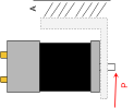
Figure 1: Shows motor, the rigid wall and the force received on the shaft of the motor, where P = 300
Appendix A:
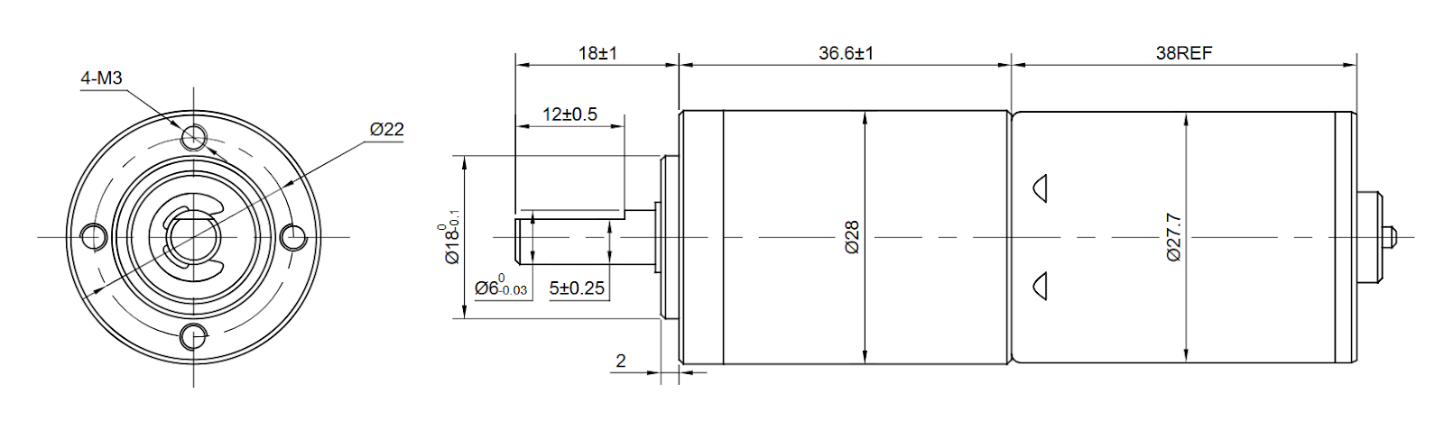
Figure #1 Dimensions of the Gear Motor in mm.
Appendix B:
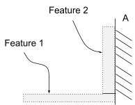
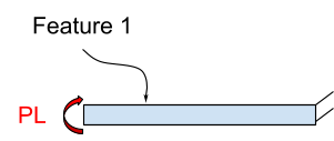
A 2D representation of a Motor Mount
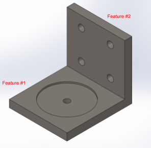
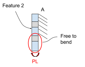
An isometric view of the motor mount.
*The description information and appendices A and B are taken directly from the Assignment description made by Dr. Fagan
My Process
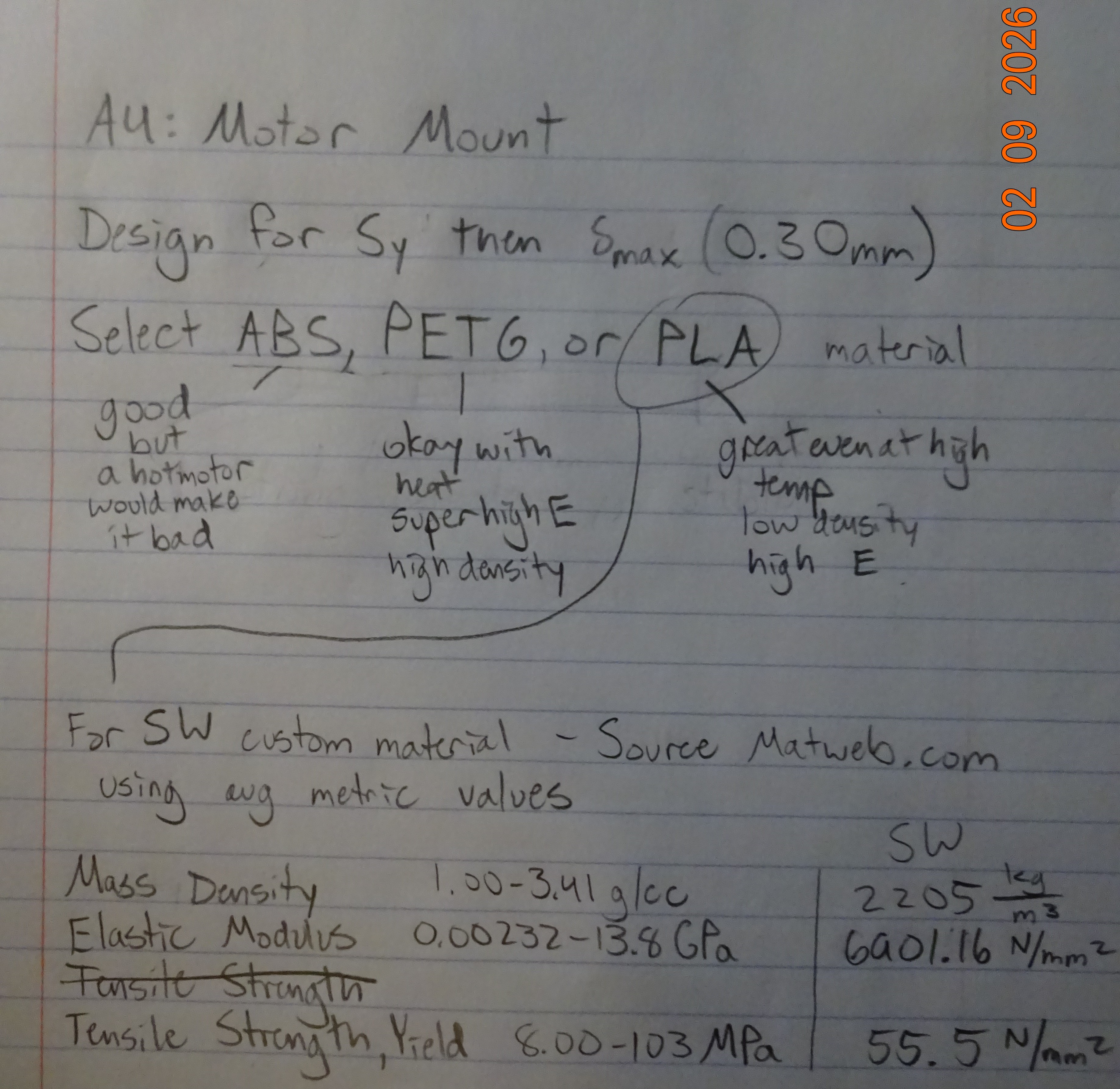
First, I made sure that I understood what material and values I would be using for my calculations and eventual CAD model. I chose to use PLA plastic, since it offers the best performance at high temperatures and is relatively low density with a good modulus of elasticity and yield strength. The heat factor seemed important since this mount will be for a motor that could get quite hot under load. The modulus of elasticity will be important for determining the design with a max deflection, and the yield strength will be important for the other design process. I decided not to use ABS despite it being the strongest of the plastics due to low performance at high temperatures. I decided not to use PETG since it has a relatively high density to the others and does not offer as much flexibility with high heat. The sources I used to get this information are linked in the description above.
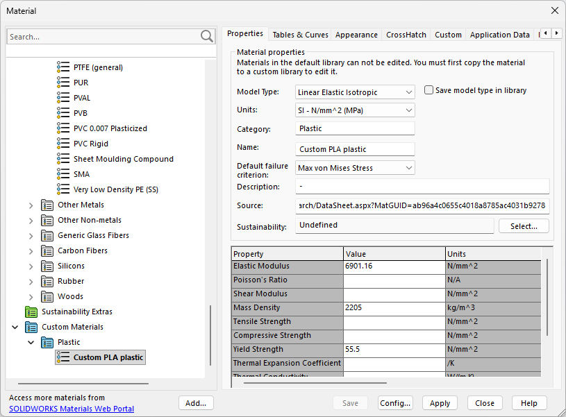
I next went ahead and added a custom plastic material into my CAD software of choice, SolidWorks. I used the average values found from Matweb and then converted to the units needed for SolidWorks in SI units. I then input my data, linked my source, and gave it a name so that I could find and use the material later. These will be the same values I use in my hand calculations and design process.
Feature 1
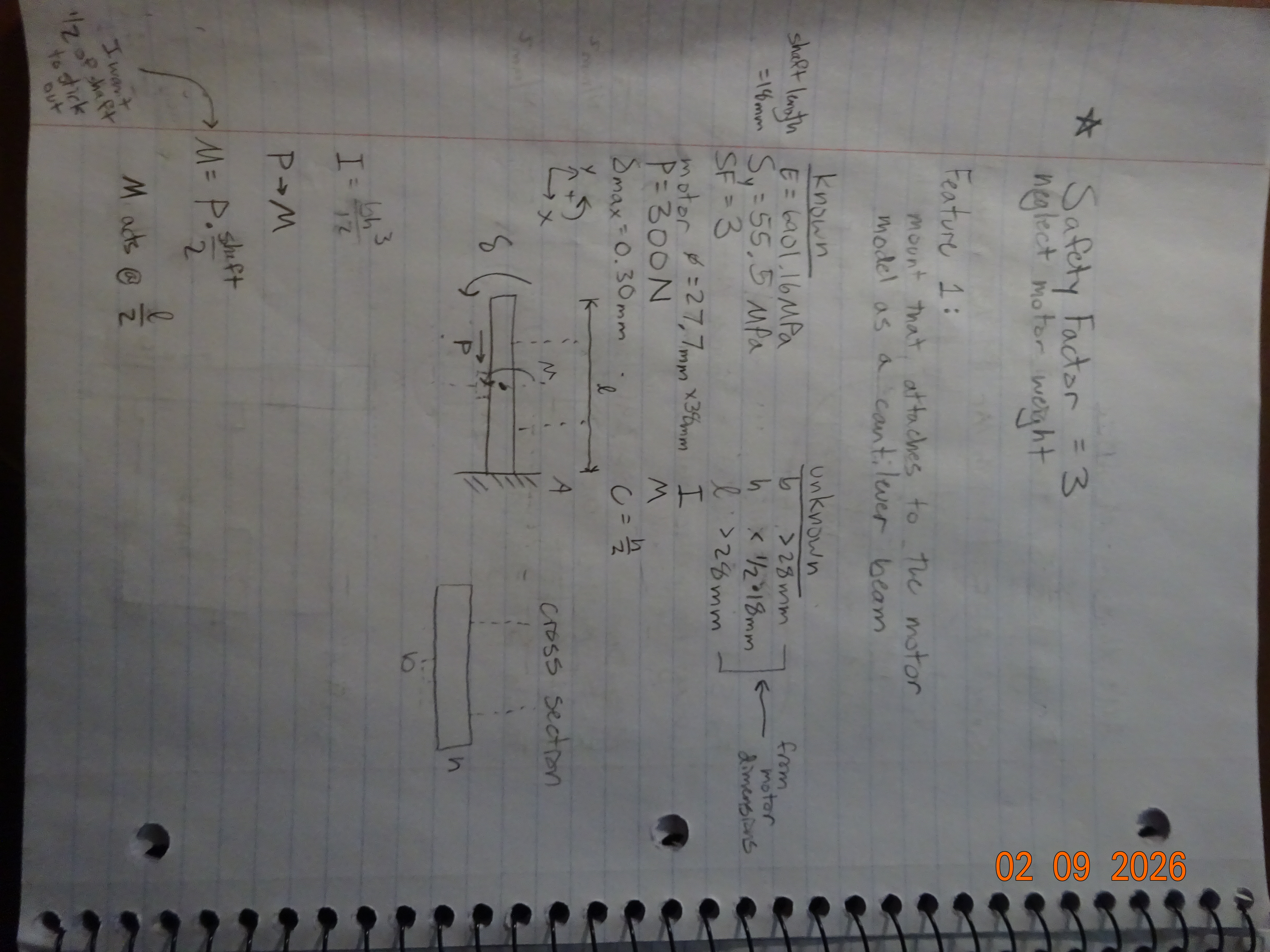
The first step I took to this design was really stopping to think about how I would analyze the two different features. At first, I was a little bit confused by the orientation of the description, but then realized that the orientation did not effect the design process much since we were neglecting the weight of the motor.
The first step was to simply write down the known and unknown variables for the design of feature one. I used the material properties I found earlier for PLA as well as some dimensions of the motor shaft and motor diameter. At first, I had too many unknown values, so I had to make some assumptions and later test some initial values. The next step for feature one was to turn the load on the shaft into a moment that could be applied to the beam analysis. I knew that I wanted about half of the motor's shaft to be able to stick out of the motor mount, so I calculated the moment 'M' as P times half the shaft length. Next, I remembered back to my research of motor mounts and found that most were simple geometry and many had just a square face. I used this to determine that my 'b' and 'l' values of feature one would be equal to each other. I also knew that these lengths would have to be longer than the diameter of the motor, so I went ahead and wrote down that they would have to be larger than the 27.7mm diameter. The last constraint I made was for the height 'h' value of the feature. Like I said previously, I wanted at least half the motor shaft to poke through, and so the height of the beam could be no more than half of the 18mm shaft length. I drew up my free body diagram, which I rotated 90 degrees to better visualize the cantilever beam model and proceeded to start the calculations for the two design processes.
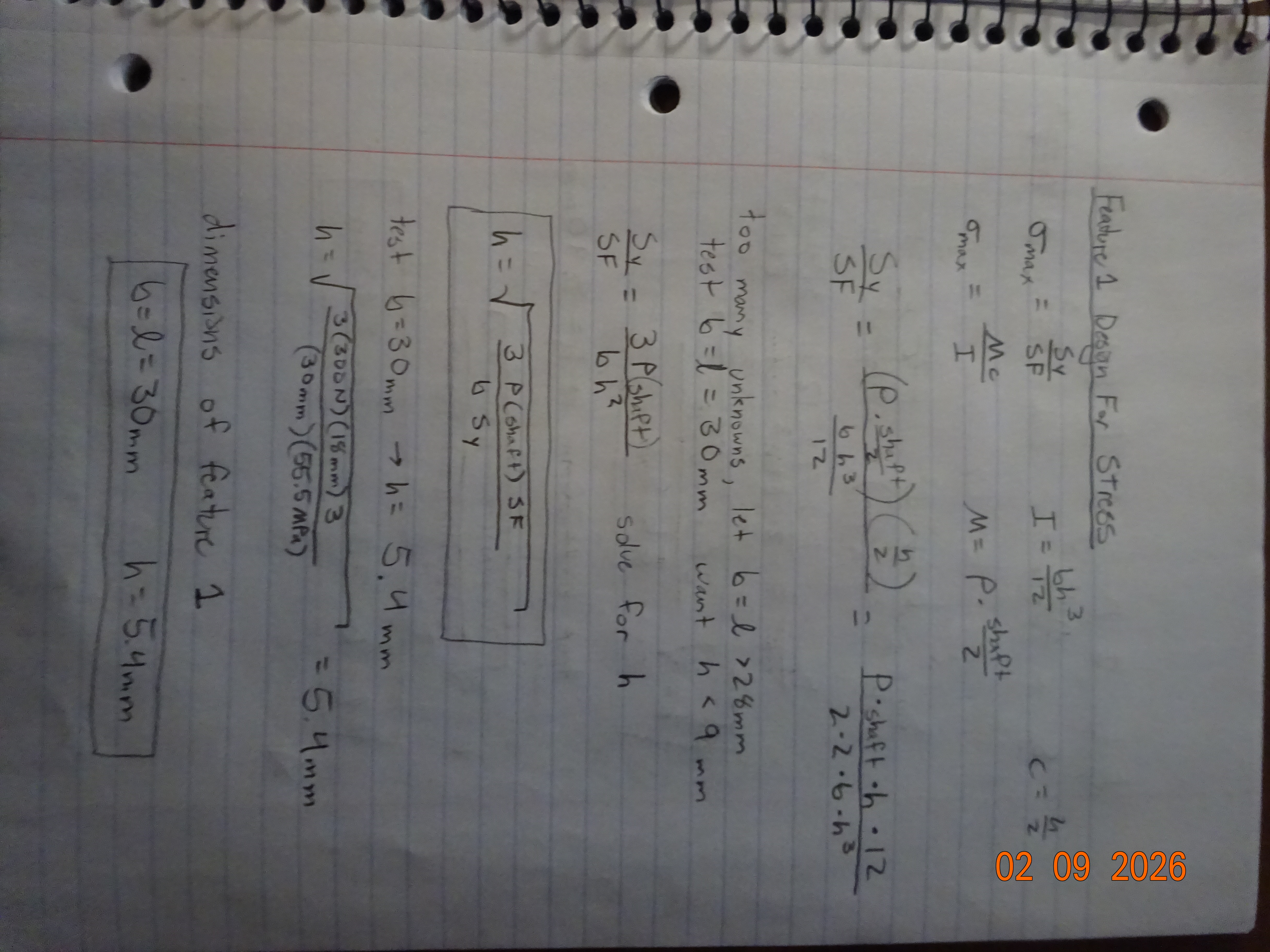
Feature 1 Design for Stress
The stress design required a few different equations, so I laid them all out at the top of my page. With a little bit of algebra, I combined the equations to get a single equation with the variables I wrote down previously. At this point, I still had too many unknown variables, so I made the decision to start testing with my 'b' and 'l' values set equal to 30mm which would be just larger than the diameter of the motor. With that, I was finally down to one variable which was 'h.' I was okay letting 'h' be the driven variable in the beam design, but was careful to make sure that the value still fit my earlier constraint of being less than half the shaft length (9mm). After plugging the numerical values into the symbolic equation, I was happy to find that the height value was 5.4mm for the stress analysis.
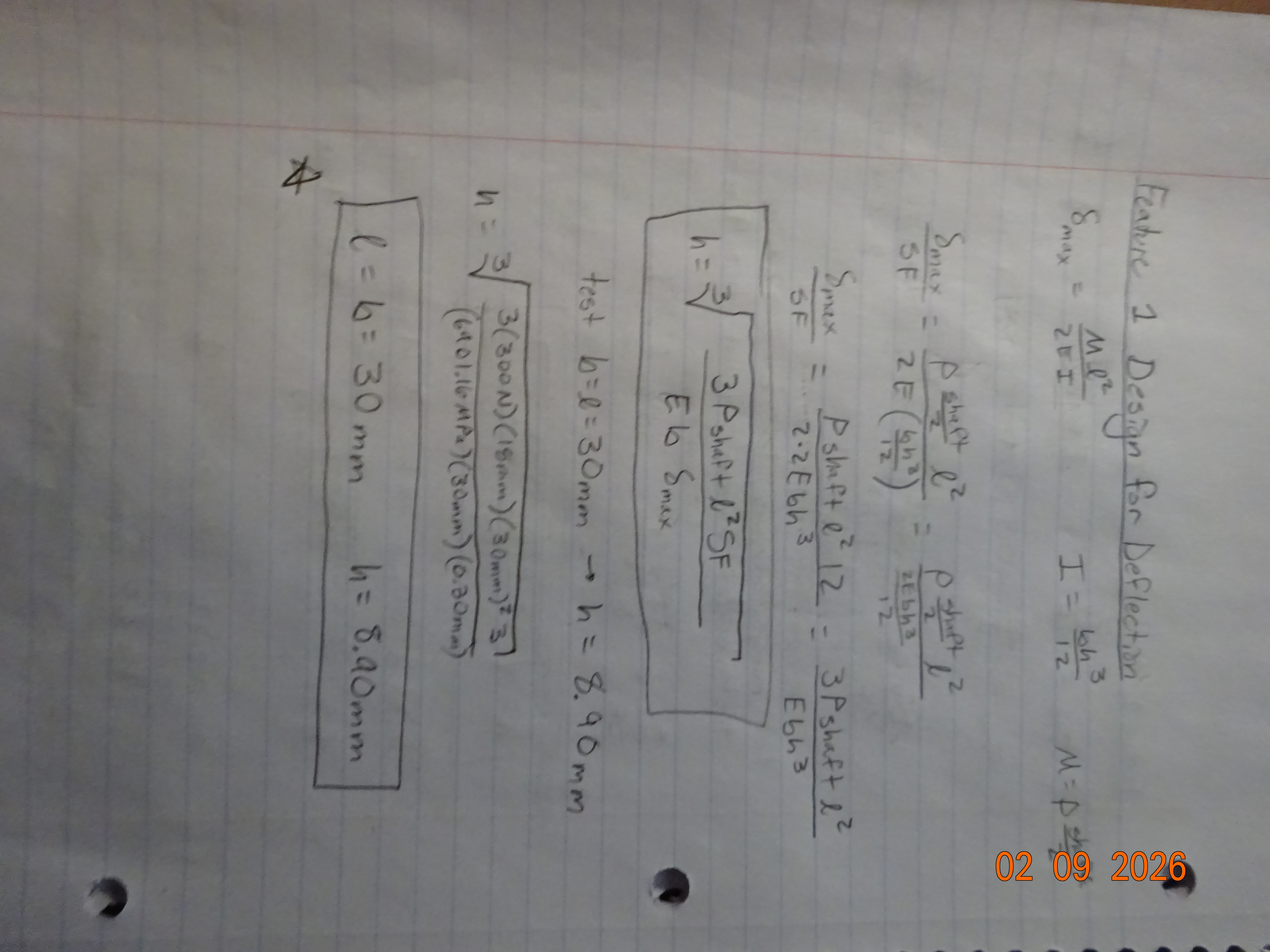
Feature 1 Design for Deflection
For the second design process, I used the equations for deflection in a cantilever beam. I used the same variables, and after algebraically manipulating the equations, I got a new formula for h. Again, I utilized my assumption of 'b' and 'l' being equal to 30mm and found an 'h' value. This process got me a height value of 8.9mm. Since my final design will be subject to both stress and strain I knew I would have to later utilize the larger of the two height values. For this reason, I put a star next to the larger dimensions to remind myself to come back and use those values.
Feature 2
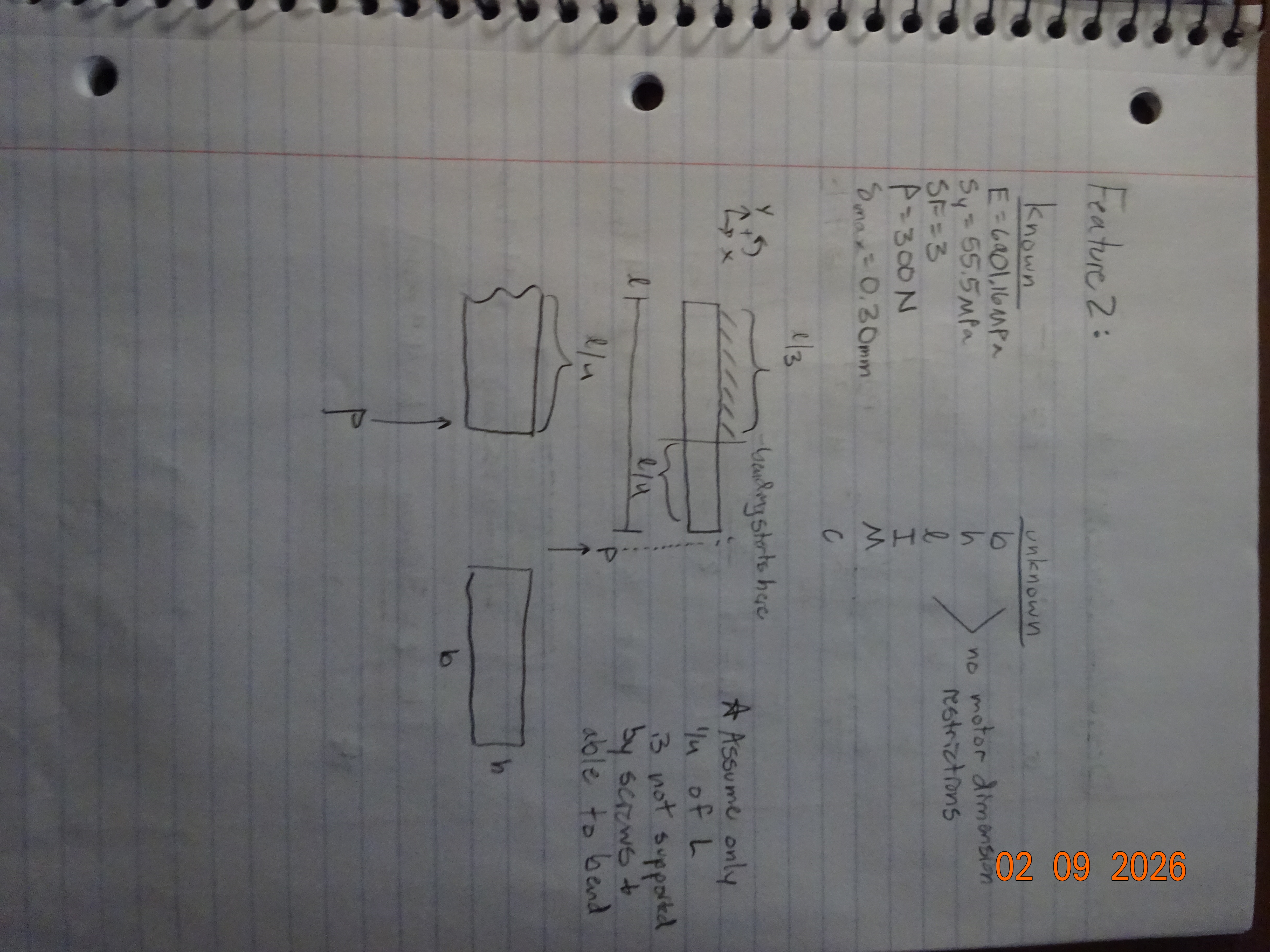
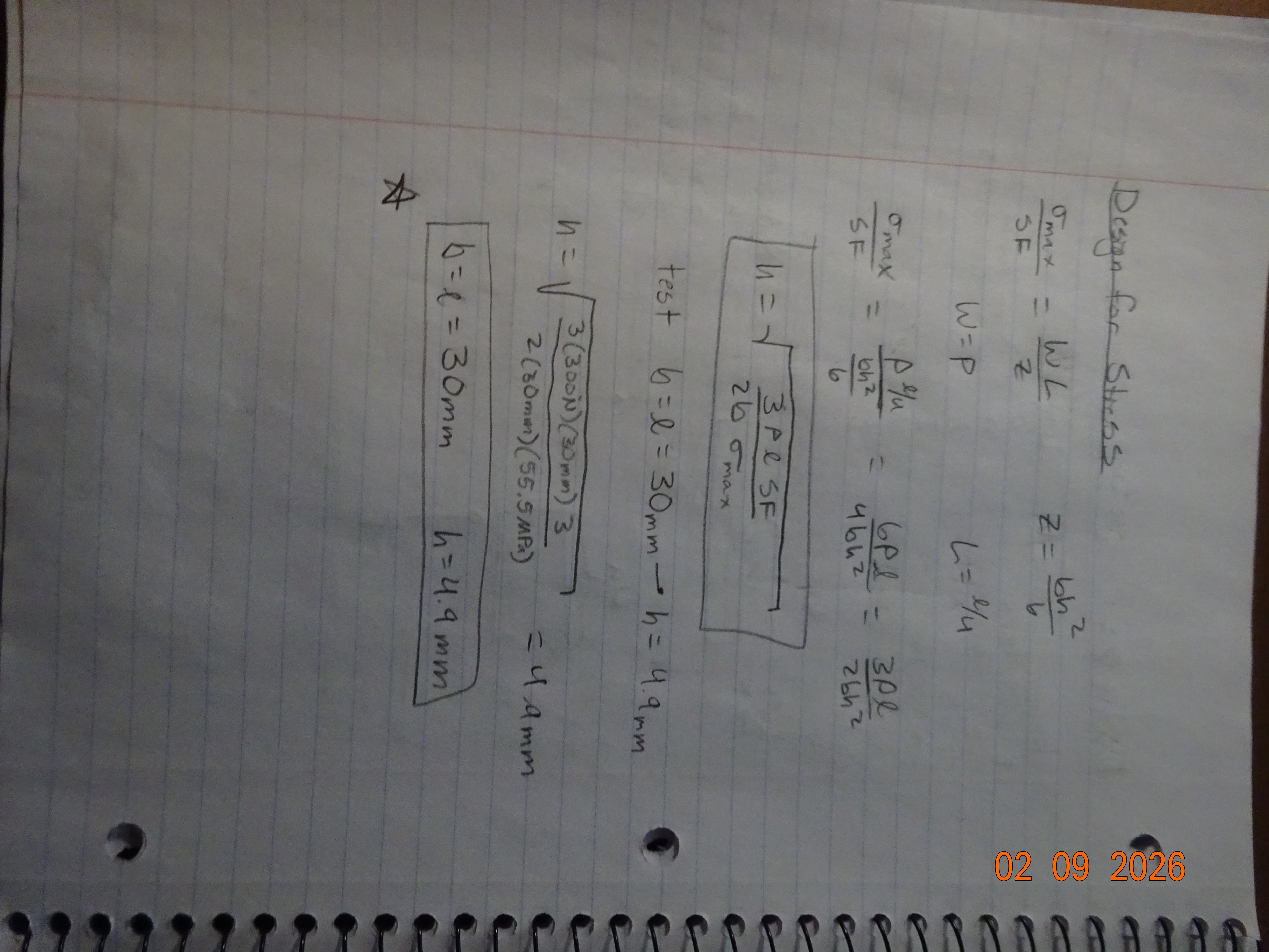
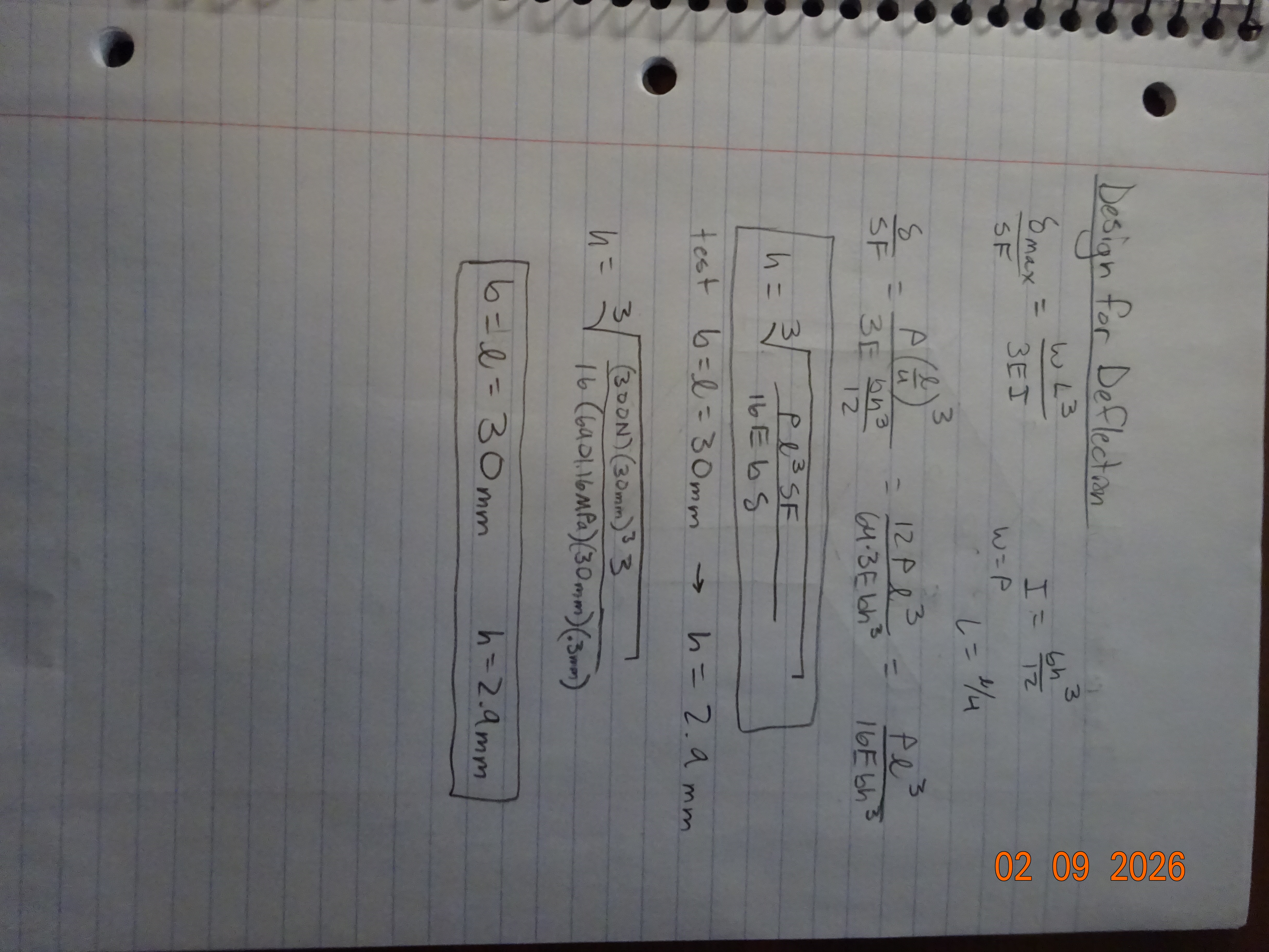
For feature two, I took the same approach as I did for feature one with just some slight revisions. I wrote down all my known and unknown variables and then made a free body diagram. The main difference for feature two was that a majority of the beam was being supported by the rigid wall A. Since this part of the motor mount would not be subject to bending, I made a section and made the decision to treat only the last fourth of feature two to be subject to bending. The other three fourths would be more rigid due to the screws holding it flush to wall A. I was then able to move onto the two design processes.
Feature 2 Design for Stress
For feature two, the load P was acting less like a bending moment and more like a load at the free end of the cantilever beam. Since there was now no moment to be considered, I utilized a different equation for the stress on a cantilever beam. This equation was simpler than for feature one, but I had to make sure that I was using a fourth of the overall length in the equation. I algebraically solved for 'h' and then reused my same values for 'b' and 'l' since I thought it would make most sense to use the same square layout and lengths. Doing this, I was able to solve for a height value of 4.9mm.
Feature 2 Design for Deflection
Similarly to the stress analysis, I needed to utilize a different equation for the deflection of the cantilever beam model. This equation utilized a single load at the free end rather than a moment, and I was able to algebraically solve for the value of 'h' once again. I continued to utilize the value of 'b' and 'l' which was 30 mm since overall it seemed to work for all other calculations and fit my constraints. The calculation got me a height value of 2.9mm which was smaller than the stress analysis. Since I needed to use the larger of the two values, I went back and put a star next to the dimensions I would be utilizing later for the motor mount.
Isometric Sketch
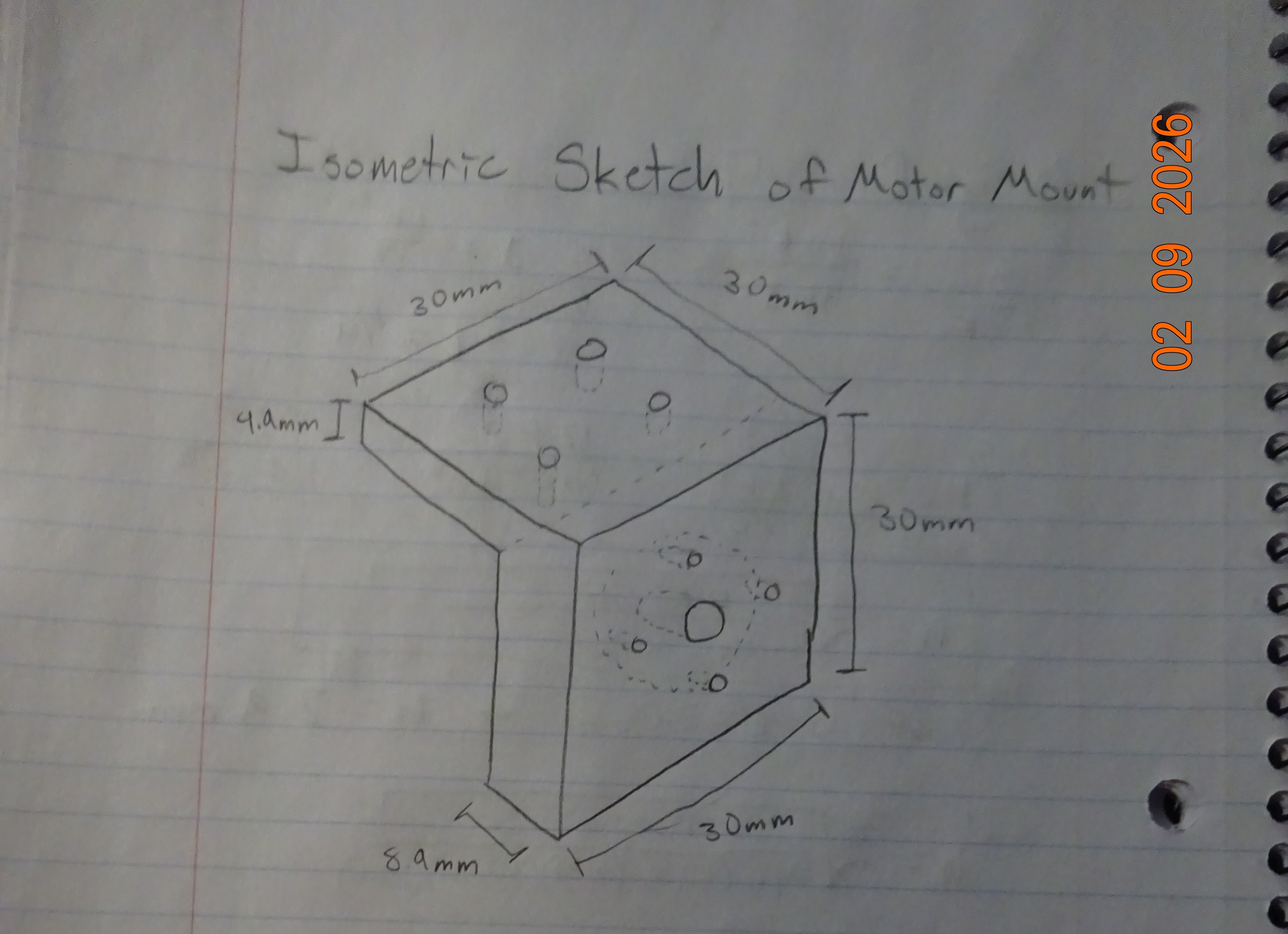
Before creating the CAD model, we were asked to make a sketch of the final motor mount design in an isometric view. I also included the dimensions I had calculated and made some rough locations for the holes that would be needed for the motor and anchoring to wall A.
CAD Model
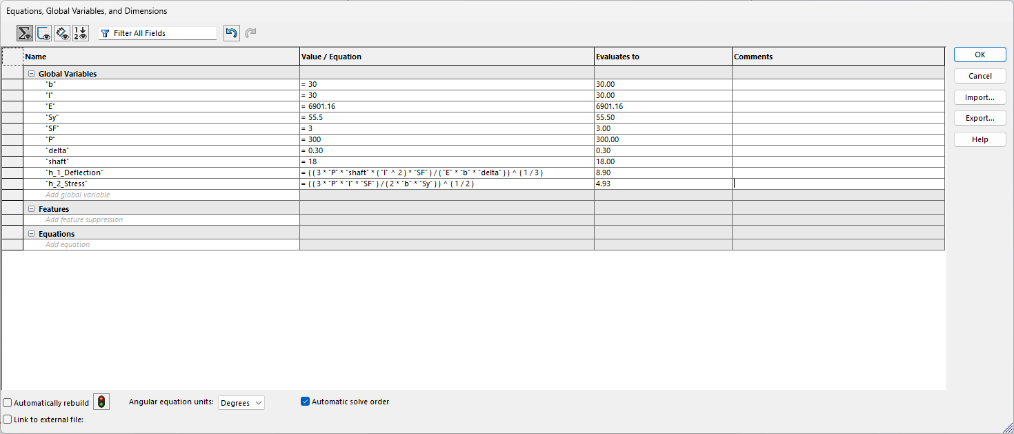
The first thing I did for the CAD model was make sure that everything was setup for me to start sketching. This meant making sure I was working in MMGS units, the material was selected as my custom PLA plastic, and I had all my parameters set up. Since I had calculated for both of the 'h' values, I kept those as driven by the 'b' and 'l' values in the CAD parameters. Doing this allows me to come back through and change the 'b' and 'l' values if I wanted to try other dimensions for the motor mount.
Once I was all set up, I started my sketch on the front plane. Since I knew that I was utilizing the same 'b' value for both features, I decided to do a single sketch of the side profile. I made sure to add each parameter to its correct dimension, and then made the extrusion
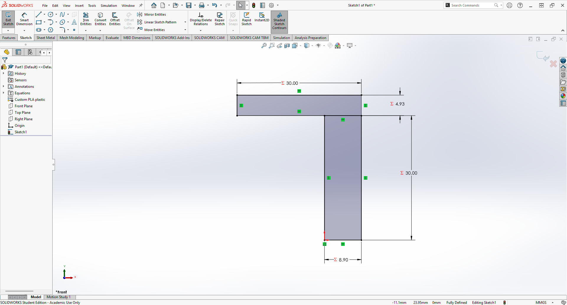
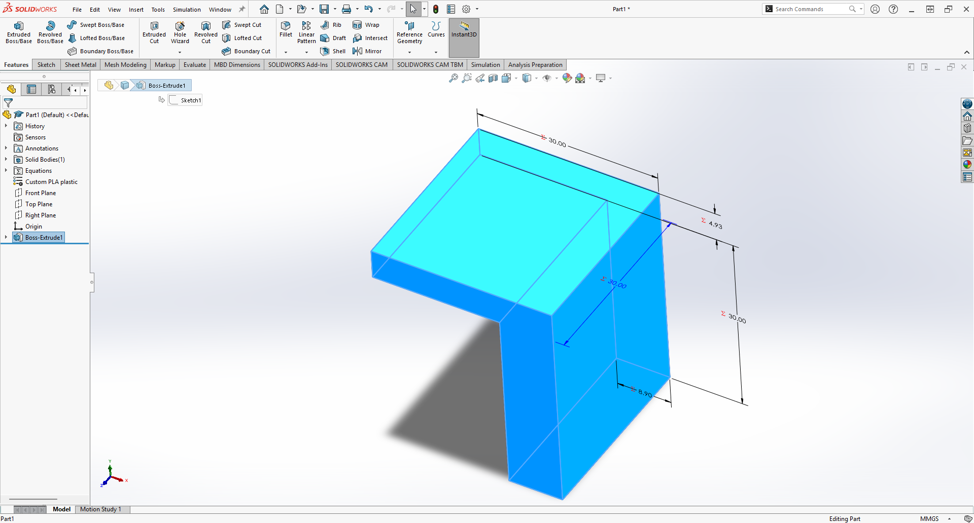
Next I needed to create the larger diameter insert from the motor that would allow the screw holes of the motor to line up flush with the motor mount. I made sure that the hole was centered on the face of feature one and made the depth match the dimension given for the motor.
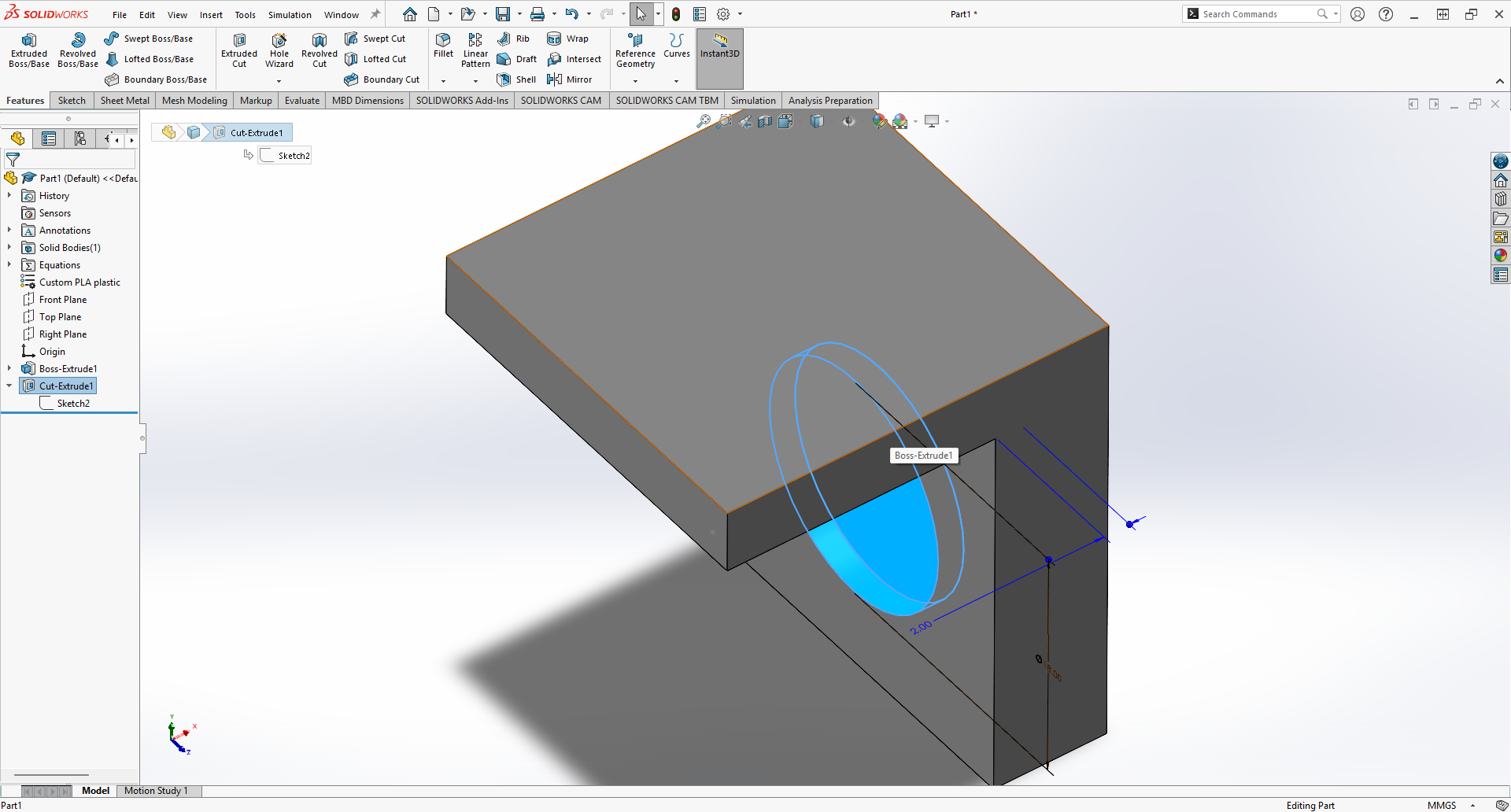
After that, I needed to create the through holes for the motor shaft and motor screws. I decided to make these holes at the same time since they were all through holes, and I made sure to follow the dimensions given from the motor. One thing I found interesting as I tried to make the extrusion of the holes was an error that was making a geometric thickness equal 0. As it turned out, the depth I had added to make the motor sit flush was reaching the diameter of the screw holes. To fix this, I simply changed the depth hole's diameter to its lower tolerance bound.
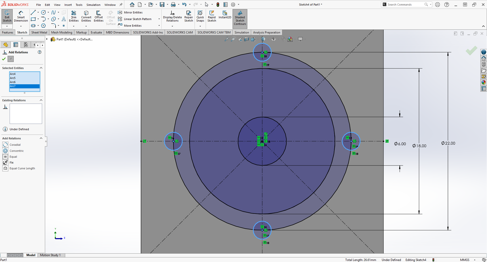
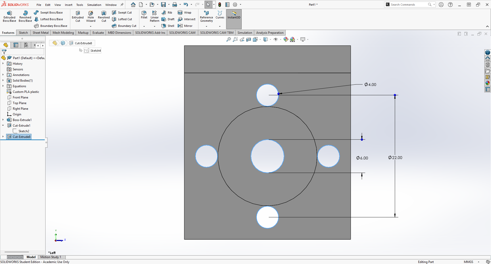
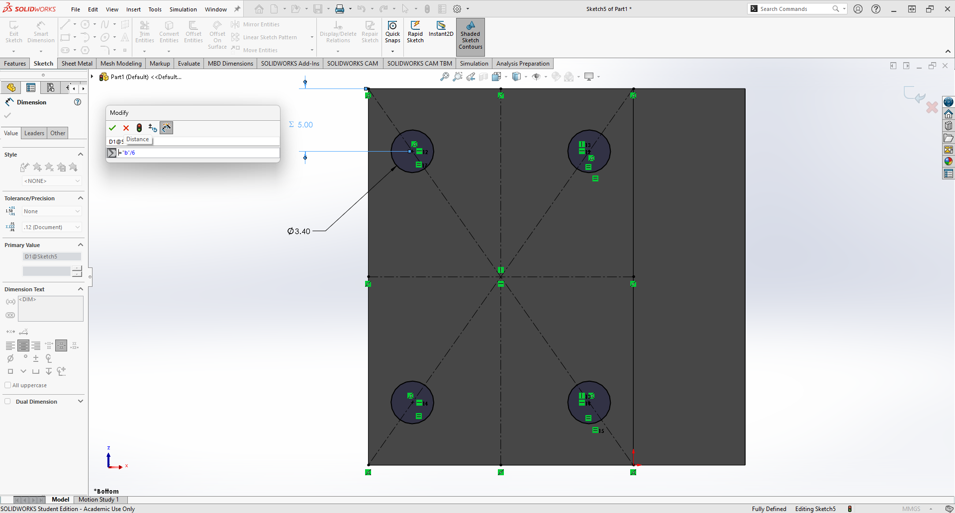
The final feature I needed to add to the motor mount was the holes for the screws that would attach to wall A. I chose to do four holes and used lots of constraints to make a symmetric layout on feature two. I then made their diameter 3.4mm as given in the assignment.
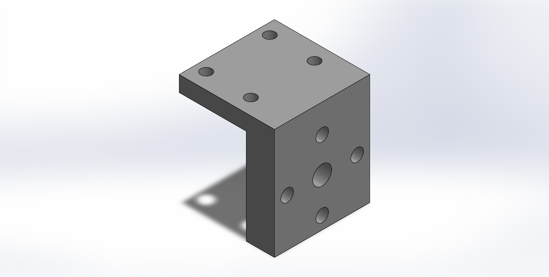
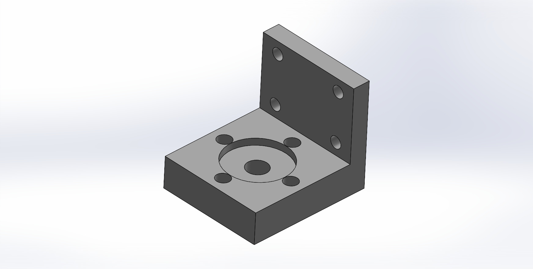
Here are the final snapshots of the motor mount. The first is the Isometric View side by side with my hand sketch. These are followed by another snapshot of the opposite side of the motor mount so see the geometry of the diameter where the motor sits in the mount.
Additional Modeling
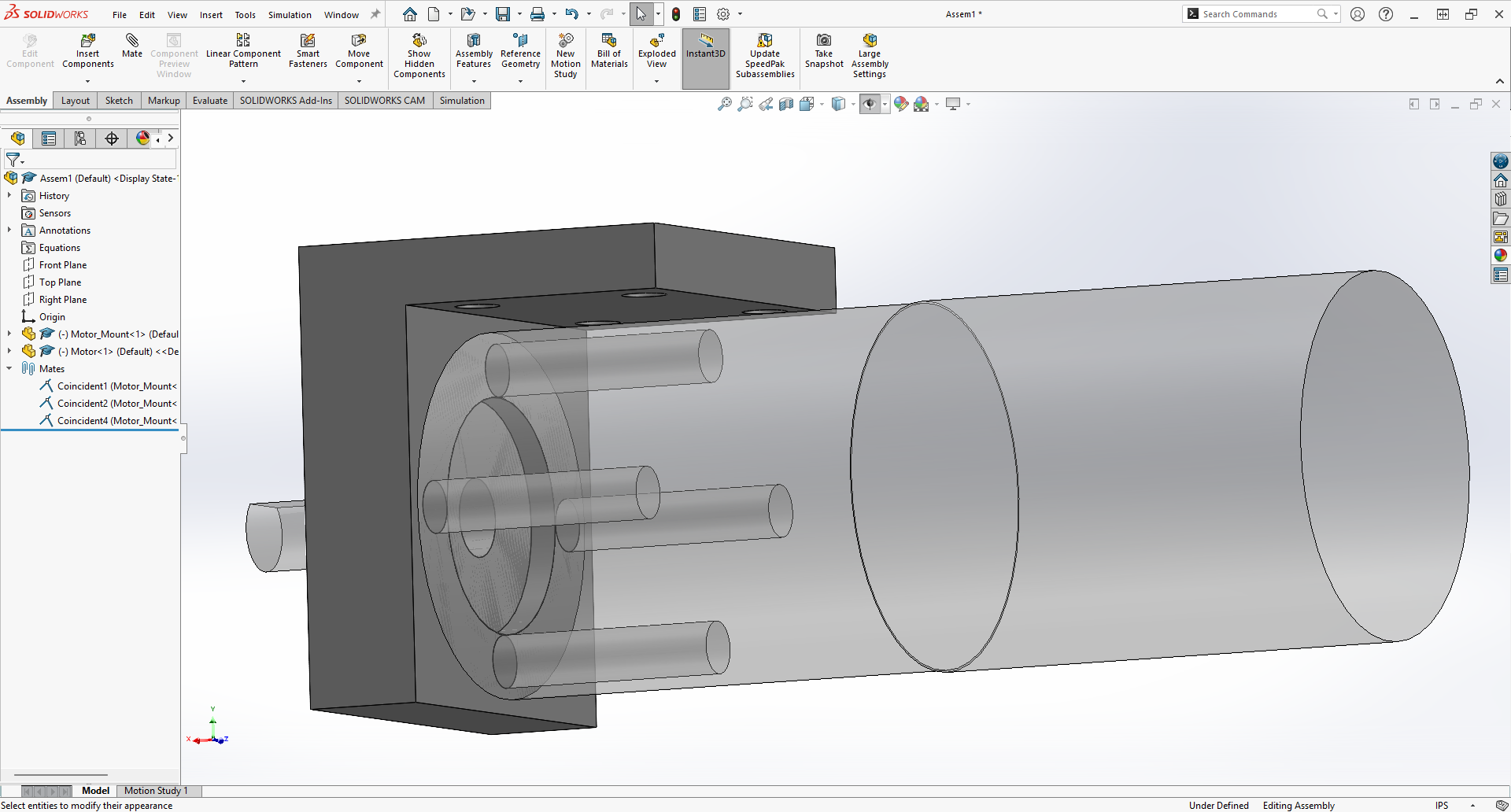
For my own interest, I chose to mock up a very rough CAD model of the motor to see how the motor mount would look like with the motor. I am not including the process of modeling the motor, but I followed the dimensions given in Appendix A. I will also attach a .zip file with the assembly at the end of this page that includes both the motor and motor mount files in it. For easier viewing in the snapshot, I made the motor transparent.
Here are some of the files associated with Assignment #4
Appendix C
Motor Mount Research:
Part of this assignment required students to look up and observe different designs for motor mounts. Below will be a list with links to different sources that I found through my research that influenced my final design.
- Model Motor Mount
- Motor Mounting Bracket In SolidWorks Sheet Metal
- 3D Printed Motor Mount for 22-23mm motors, Stick Style
- How To Make 775Dc Motor Mount /Bracket At Home | DIY Motor Mount For DC Motors | By- CreativeShivaji
- 1 Metal L Shaped Motor Mount, Rc Motor Base, Metal Motor Mount for 370 380 390 2030 2040 2435 Motors