My Assignments
Use the links below to view each assignment!
Unit 2: Strategies
Assignment 3a: Engineering Disaster
Assignment 3: Concepts
Assignment 4a: Lead Screws
Assignment 4: Modules Phase
Assignment 5a: Research Engineering Advances
Assignment 5: Components
Assignment 6: Drawings
Assignment #5: Components
Problem Statement
The purpose of my design is to make a competitively priced, vibration resistant action camera mount primarily for Drone applications. This mount should also useful for extreme sports and Vehicle racing. The mounting system must be simple to use and effective at damping impacts and vibrations that cause a "jello-like" image when filming. The camera holder will hold a small action camera that is roughly 38 x 38 x 36 mm an weighs about 74g.
Assumptions
Some assumptions I am making is that the product must be lightweight and easy to position a camera to point a specific direction. I am also assuming the customer will want the setup time to be short and easy, while the camera remains firmly pointed in the correct direction.
Decision Matrix: Selecting a Module
Now is the time to select which module best suits the purposes and constraints of the functional requirements. This decision matrix will let us know which module best suits the purposes of the product.
The metrics I used to choose the best design are Cost, Manufacturability, Durability, Simplicity, and Weight. Cost was weighted most heavily, as this product is intended to be very competitive with similar products. Manufacturability was also weighted heavily becuase involved processes, such as injection molding, have very high initial costs before the first unit is sold. Durability was given a 20% weight because it is very important, especially when used with a drone that crash at speeds upward of fifty miles per hour. Simplicity and Weight received lower ratings because all three designs are relatively simple to make and within ounces of one another in weight.
Module #1 pulls ahead of the other two. It's level of simplicity allows it to be manufactured much more easily and quickly. Module #1 does have slightly less durable construction. The other designs solve this issue, but these considerations increase the complexity of manufacturing and costs in materials.
Components
Download all of the Component CAD Files Here!
Critical Component #1
By far the simplest, this module is a simple hinge mount to the camera with two strong plates bonded to the intermediate foam(in Blue). The foam will be a closed cell polyurethane material, which is very durable and very common for similar applications. The mount, upper plate, and lower plate will be made of ABS Plastic. On the upper plate and bottom of the camera holder, fins with holes are fixed together by a fastener that allows the camera to pivot into position.
Critical Component #1 FRDPARRC
Critical Component #2
This is the Camera mount that will hold the camera in place. The camera fits within the upper portion and the fins on the bottom interface with the base to make a complete hinge. There must be adequate friction between the fins of the mount and the base in order to hold the camera still at the desired angle.
Critical Component #2 FRDPARRC
Critical Components Assembled
Module Analysis and Calculations:
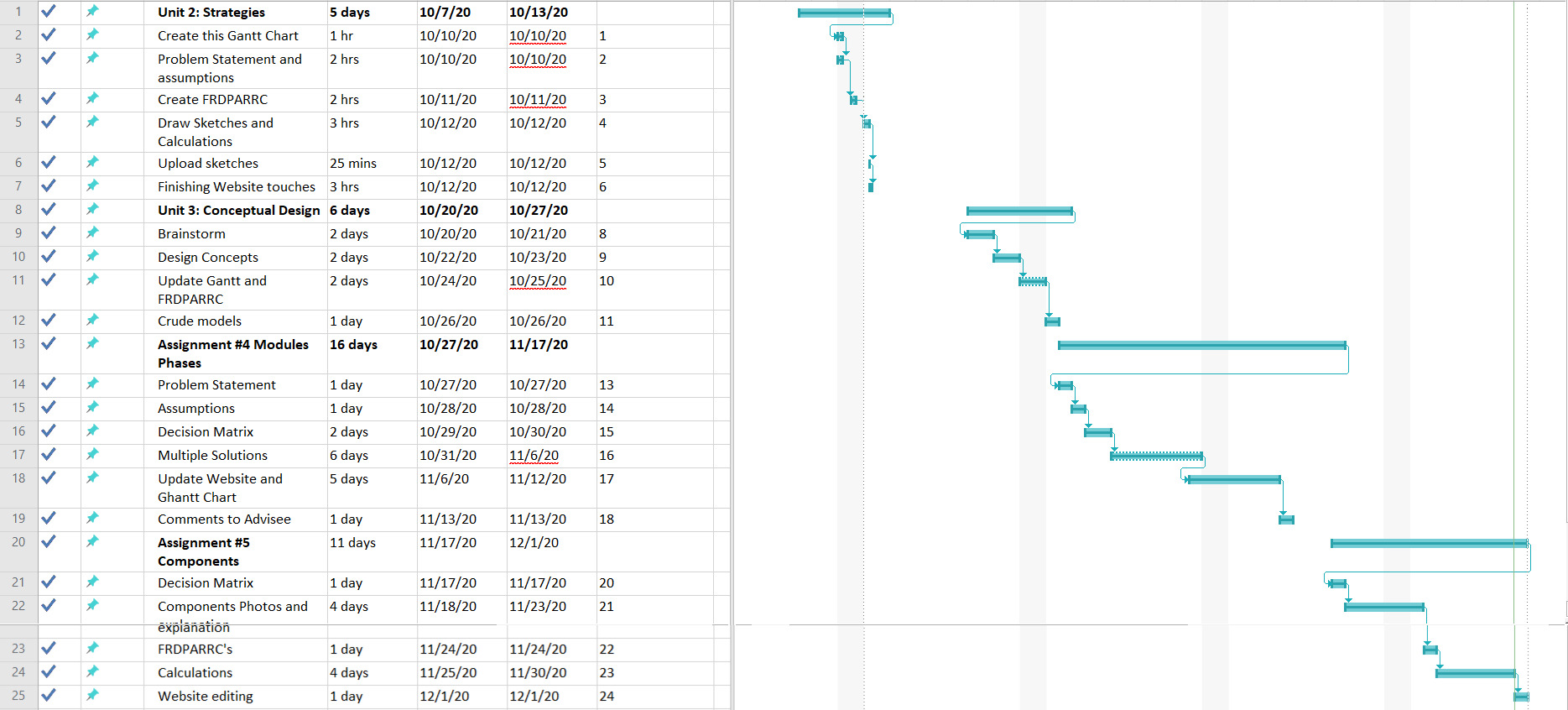
Project Plan: Gantt Chart

Lessons Learned
-Improving CAD skill.
-Doing analyses with specific materials I chose.
-Choosing materials to sustain the loads the system undergoes.
Activities Date and Time
-Setup, Decision Matrix: 11/29/20 from 11am-3pm.
-New Caclulations: 11/29/20 from 5-8pm.
-Gantt Chart and Finishing touches: 12/1/20 from 8am-11:59pm.
Advisee Comments
-Again, you have really done great! Looks beautiful and I love the detailed renderings.
-There is no "E" in FRDPARRC.
-Assignment #5 appears to fill all requirements.
-Doing your FRDPARRC's in Excel would really give a cleaner look.