Austin Northcutt
-Assignments-
_______________________
Assignment 2 | Assignment 3 | Assignment 4 | Assignment 5 | Assignment 6
_______________________
Assignment 3 - Concepts
Problem (updated):
The engine I have been building for the last few years now requires a wire harness. Several years of work has gone into this engine so I wanted to design and engineer a high quality durable wire harness to match the engine. In order for the harness to meet the desired quality, it must meet a few functional requirements. It must have quick-disconnect connectors that join at the firewall of the engine bay for easy removal and insertion of the engine itself. To give the wires a bit of strain relief and also mitigate noise, the harness will be concentrically twisted. Finally, the layout must be efficient, cut down on wire lengths, and also incorporate a remote pressure sensor mount for accurate data acquisition.
Assumptions:
Creating this level of
harness will result in a flexible,
durable, and modular harness that can be used for many years
to come on similar
engine platforms.
Updated Gantt Chart:

Decision Matrix:
After completion of the decision matrix, I found that the wiring harness scored the highest, and what will be pursued through the course of this project. The criteria chosen for the decision matrix revolve on what not only the customer desires, but also what I personally value since the harness is being installed on my personal engine. The top three priorities were each equally weighted as 20%. Functionality, durability, and reliability are all detrimental to the harness especially functionality. If one critical sensor fails because I mistakenly wired something incorrectly it could result in physical damage of the motor itself.

Concepts:
Layout
- The
current play for the engine harness is below.
I am keeping the ignition harness completely separate
from the main loom
because I play on upgrading to a different ignition system in
the future. Making
the extra effort to do this will allow
me to easily de-pin the cannon plug and just wire in a short
harness for the
coil packs rather than having to open up the larger 60+ wire
harness. Wire
lengths will be calculated after I have been home to create a
mock-harness out
of nylon rope. Final Layout will be done in either
Solidworks electrical or Microsoft Visio.

Bulkhead
Plate - This
is a plate that will be bolted to the firewall of the car
using small 8mm bolts
and riv-serts installed in the car. The
cannon plug connectors I am installing on the harness mount
and attach
here. Making a
bulkhead like this allows
for easy access to disconnecting and reconnecting the engine
harness when need
be.


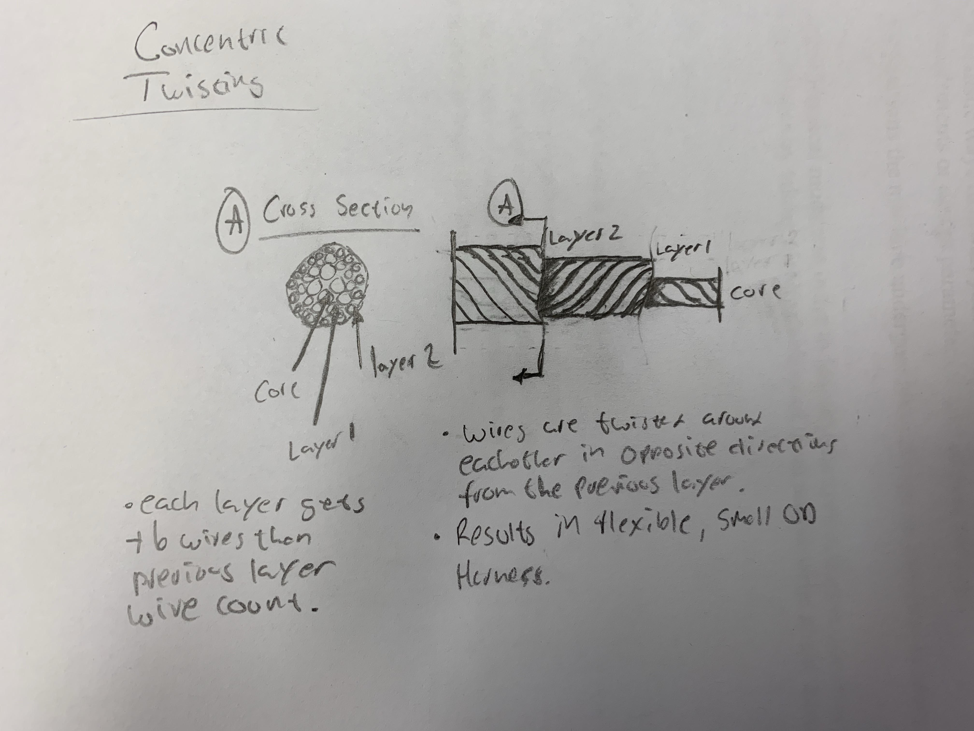
Concentric Twisting - Concentric twisting is the method of wrapping layers of wire around the previous wires in opposite directions. Doing this reduces noise in the harness and essentially functions as a Faraday cage, protecting inner wires. It also results in a very flexible harness that can bend in almost any direction desired.

Remote Sensor Mount - Remote mounting pressure sensors is always a good idea because they are susceptible to the harsh vibrations the engine creates. Each sensor will be secured with a rubber lined P-Clip bolted to this bracket which is also bolted to the driver side strut tower of the car.


Lessons Learned:
-How
to
create a decision matrix.
-I am getting faster at brainstorming for the FR Charts.
-More research done on concentric twisting wires. Made a few physical
models as practice and
have the technique down.
-I struggled for a bit with the formulas, but I have them down
now. Assignment 3
will feature all the formulas I
will apply seeing as all my sensors and the engine itself is
at home in
Raleigh. Once I
can take measurements I
will be able to apply the formulas for all voltage
calculations, concentric
twist layers, and static equations for the bulkhead and sensor
mount.
Activity Log:
- 2/16/2019 (12:00pm – 3:00pm) Assignment started; Decision matrix made; Rough FR tables made.
- 2/17/2019 (2:30pm – 5:00pm) Sketches created for concepts.
- 2/18/2019 (10:00am – 12:00pm) Final drafts of FR Tables created. Paragraphs typed for prompts.
- 2/20/2019 (6:45pm – 11:00pm) Website updated, Comments,
Gantt updated
Comments:
William Hinson:
-I really like your solid models of everything.
-Try organizing your assignment by concept instead of category
so it flows
better.
-When I looked at your page (2/20/2019 8:45pm) you were
missing your decision
matrix. I would
double check this before
8:00am tomorrow.
James Neal:
-I really like how organized and aesthetically pleasing your
website is.
-Try having your FR charts coupled with the concept you are describing to make it a bit easier to understand and follow.
-Update your problem statement and assumptions before 8am
tomorrow!